Lighting apparatus, display apparatus, projection display apparatus, lighting method, image display method and image projection method

Inactive Publication Date: 2009-05-28
PANASONIC CORP
View PDF1 Cites 12 Cited by
  • Summary
  • Abstract
  • Description
  • Claims
  • Application Information

AI Technical Summary

Benefits of technology

[0008]In order to solve the above problems, an object of the present invention is to provide a lighting apparatus, the light utilization efficiency of which is improved by a simple optical system.
[0010]According to this construction, by dividing the lights in the different wavelength ranges into the spatially different irradiation regions with the separation regions and successively switching to the different irradiation regions at the specified time intervals, the illumination lights can be immediately moved to the specified irradiation regions at the specified time intervals to be constantly present in the irradiation regions without requiring a complicated optical system for moving the illumination lights at a constant speed as in the prior art. Therefore, light utilization efficiency can be improved by a simple optical system.

Problems solved by technology

This method has had a problem that light utilization efficiency for transmission through the filters is reduced to one third.
Therefore, there has been a problem of causing a loss in the light utilization efficiency.

Method used


Image

  • Lighting apparatus, display apparatus, projection display apparatus, lighting method, image display method and image projection method
  • Lighting apparatus, display apparatus, projection display apparatus, lighting method, image display method and image projection method
  • Lighting apparatus, display apparatus, projection display apparatus, lighting method, image display method and image projection method

Examples


first embodiment

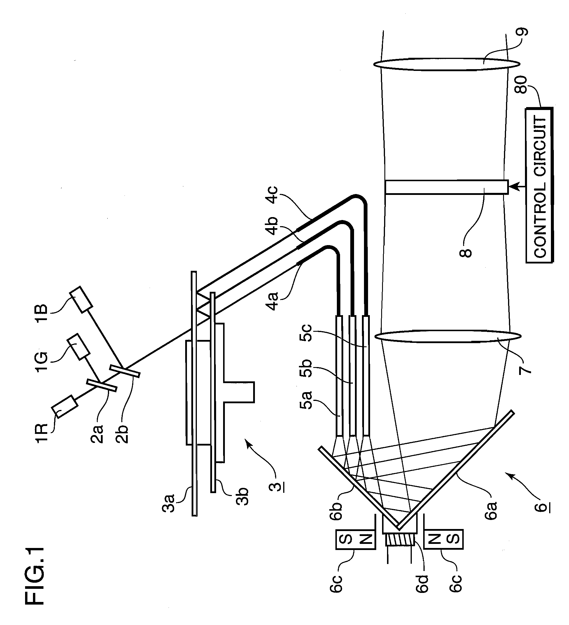
[0029]FIG. 1 is a section showing a schematic construction of a projection display apparatus according to a first embodiment of the invention. In FIG. 1, identified by 1R is a red laser light source for emitting red laser light, by 1G a green laser light source for emitting green laser light and by 1B a blue laser light source for emitting blue laser light.

[0030]Identified by 2a, 2b are dichroic mirrors, wherein the dichroic mirror 2a transmits red light while reflecting green light and the dichroic mirror 2b reflects blue light while transmitting red and green lights.

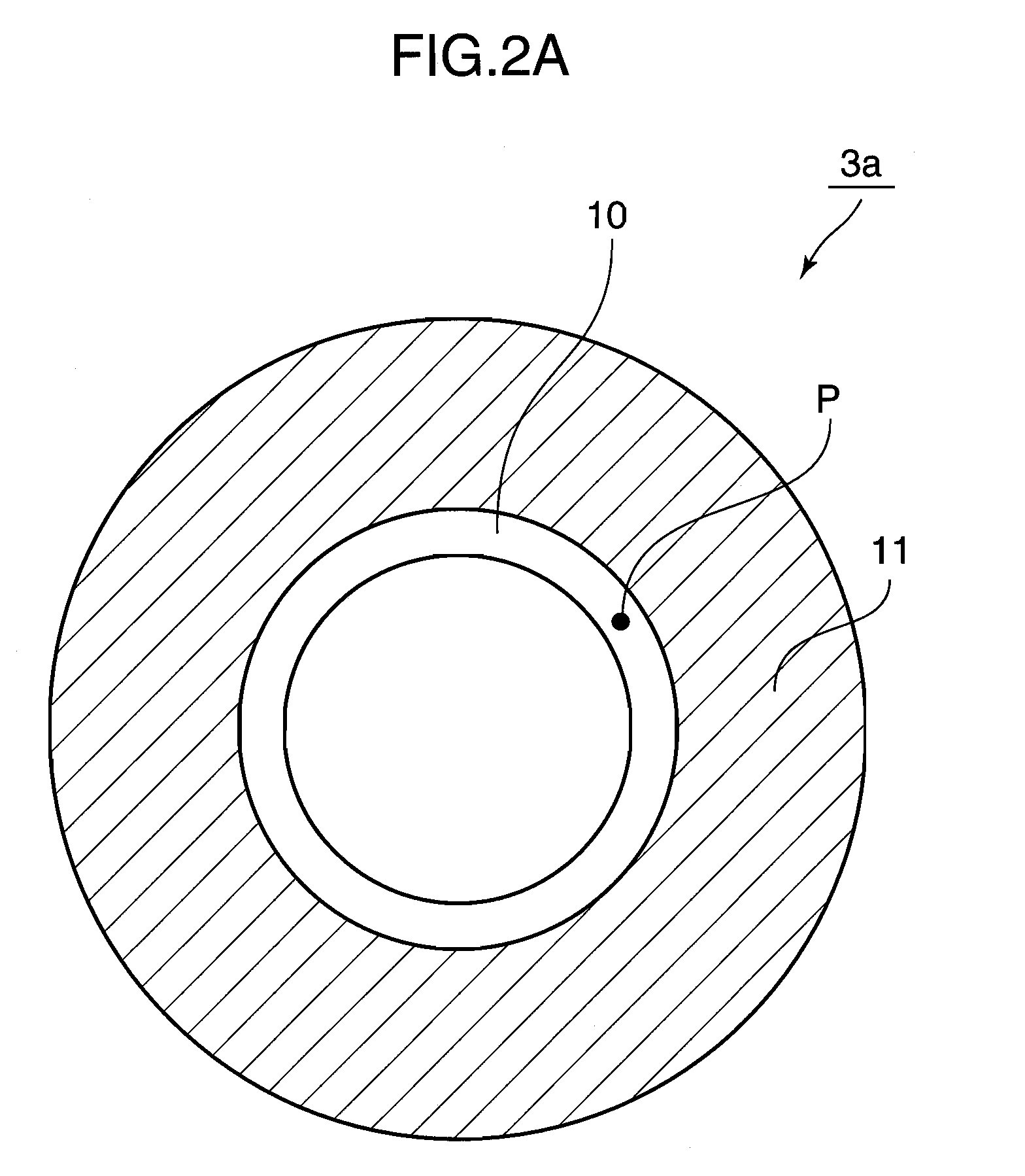
[0031]Identified by 3 is a color wheel made up of first and second disc bodies 3a, 3b and disposed on optical paths of the lights emitted from the light sources 1R, 1G and 1B.

[0032]Identified by 4a, 4b and 4c are light guides, each of which receives any one of the color lights having passed through the color wheel 3 at one end and emits it from the other end.

[0033]Identified by 5a, 5b and 5c are rod integrators, which ...

second embodiment

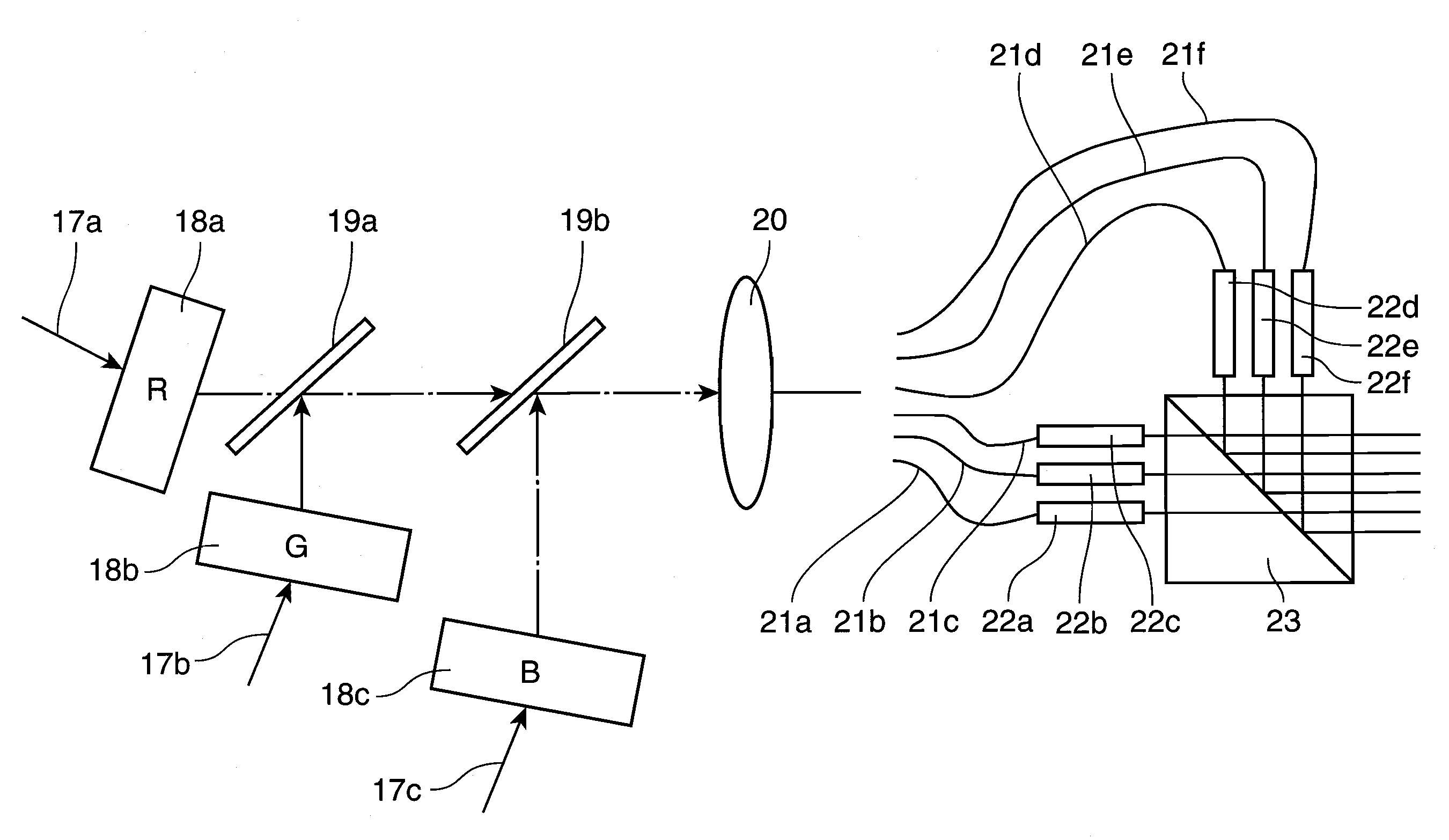
[0066]FIG. 8 is a section showing a schematic construction of an optical path switching member in a projection display apparatus according to a second embodiment of the invention. In FIG. 8, identified by 17a, 17b and 17c are red, green and blue lights emitted from unillustrated three laser light sources. Identified by 18a, 18b and 18c are light deflectors, which are preferably acousto-optical devices, electro-optical devices, galvanometer mirrors or micromirror devices. The three light deflectors 18a to 18c change propagation directions of incident lights by diffracting, refracting or reflecting action in accordance with external inputs. Identified by 19a, 19b are dichroic mirrors, by 20 a lens, by 21a to 21f six light guides and by 22a to 22f six rod integrators. Three rod integrators are vertically arranged and three rod integrators are transversely arranged, i.e. a total of six rod integrators are arranged such that longitudinal side surfaces thereof opposed to each other at a s...

third embodiment

[0071]FIG. 9 is a section showing a schematic construction of an optical path switching member in a projection display apparatus according to a third embodiment of the invention. In the third embodiment, light emerges from a transmission surface of a second disc body while undergoing multiple reflections between rotating first and second disc bodies and is incident on a light guide to switch an optical path. Further, the third embodiment eliminates the need for dichroic mirrors as used in the first embodiment of the present invention by causing lights emitted from light sources of three colors, i.e. red, green and blue to be incident at different positions of the first disc body.

[0072]In FIG. 9, identified by 24 is a color wheel made up of first and second disc bodies 24a, 24b. The first and second disc bodies 24a, 24b rotate while being fixed to a rotary shaft of a motor 24c with the centers thereof aligned and a specified clearance defined therebetween. Identified by 25R is red li...


PUM


Abstract

Red light emitted from a red laser light source, green light emitted from a green laser light source and blue light emitted from a blue laser light source are incident on a first disc body of a color wheel, are transmitted or reflected in conformity with the colors of the lights in wavelength selecting regions of a second disc body every time the color wheel performs a predetermined rotation. AS being reflected by the first disc body, the lights are divided into different positions to be emitted from the color wheel and irradiated to irradiation regions successively switched by an upward or downward reciprocal movement of a mirror group.

Description

TECHNOLOGICAL FIELD[0001]The present invention relates to lighting apparatus and method for lighting color image display elements, a display apparatus and a projection display apparatus including the lighting apparatus, and an image display method and an image projection method using the lighting method.BACKGROUND ART[0002]Liquid crystal display apparatuses using large-size liquid crystal panels and projection or rear-projection display apparatuses using transmissive / reflective liquid crystal elements or spatial light modulation elements such as micromirror devices are known as large screen display apparatuses. For the formation of a color image, there are a type of projection and rear-projection display apparatuses including three spatial light modulation elements in correspondence with three primary colors of red, green and blue and another type thereof for synthesizing a color image by irradiating one spatial light modulation element with lights of three primary colors in a time ...

Claims


Application Information

Patent Timeline
IPC IPC(8): G03B21/00F21V9/00
CPCH04N9/3117H04N9/3161H04N9/3164G03B33/08G03B21/206G03B21/2066H04N9/3197
Inventor ITOH, TATSUOYAMAMOTO, KAZUHISAKASAZUMI, KENICHIMIZUSHIMA, TETSURO
Owner PANASONIC CORP
Why Eureka
Try Eureka