Backlight unit, liquid-crystal display apparatus, and stacked structure

a liquid crystal display and backlight technology, applied in lighting and heating apparatus, instruments, polarising elements, etc., can solve the problems of difficult to suppress sidelobe light sufficiently, complex configuration of prism sheets, and insufficient practical use, so as to improve the luminance in the front-surface direction, ensure sufficient directivity, and sharpen the directivity of illumination light

Active Publication Date: 2015-09-17
DAI NIPPON PRINTING CO LTD
View PDF11 Cites 24 Cited by
  • Summary
  • Abstract
  • Description
  • Claims
  • Application Information

AI Technical Summary

Benefits of technology

[0059]According to the liquid-crystal display apparatus of (16), it is possible to sharpen the directivity of illumination light directed toward the liquid-crystal display panel with the aid of the light control sheet and to improve the luminance in the front-surface direction.
[0060]According to the present invention, it is possible to secure sufficiently sharp directivity with a simple configuration in a configuration of improving the light utilization efficiency of the light exiting from the primary light source using the reflective polarizing plate.
[0061]Moreover, according to the present invention, it is possible to improve the color tints of a display screen in a configuration that improves the light utilization efficiency of the light exiting from the primary light source using the reflective polarizing plate.

Problems solved by technology

However, the configuration disclosed in Patent Document 4 has a problem in that the configuration of the prism sheet becomes complex in order to supply the light exiting from the prism sheet to the liquid-crystal display panel with a sufficiently high peak light intensity and sharp directivity.
Thus, such a configuration is not sufficient for practical use.
However, in this case, it becomes difficult to suppress the sidelobe light sufficiently at an apex angle at which the peak light intensity is held at the largest value.
Thus, such a configuration is not sufficient for practical use due to color tints of the display screen.

Method used


Image

  • Backlight unit, liquid-crystal display apparatus, and stacked structure
  • Backlight unit, liquid-crystal display apparatus, and stacked structure
  • Backlight unit, liquid-crystal display apparatus, and stacked structure

Examples


first embodiment

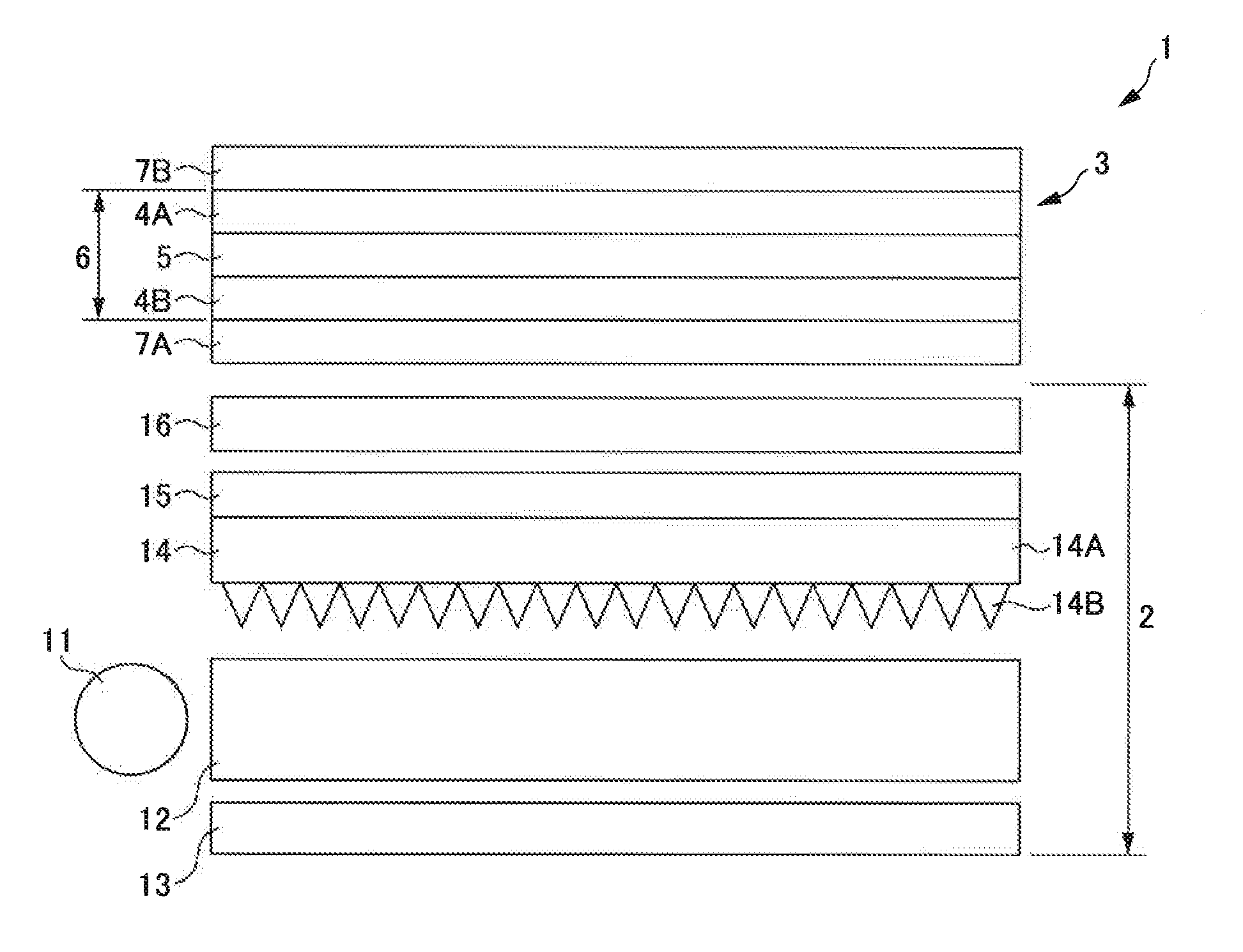
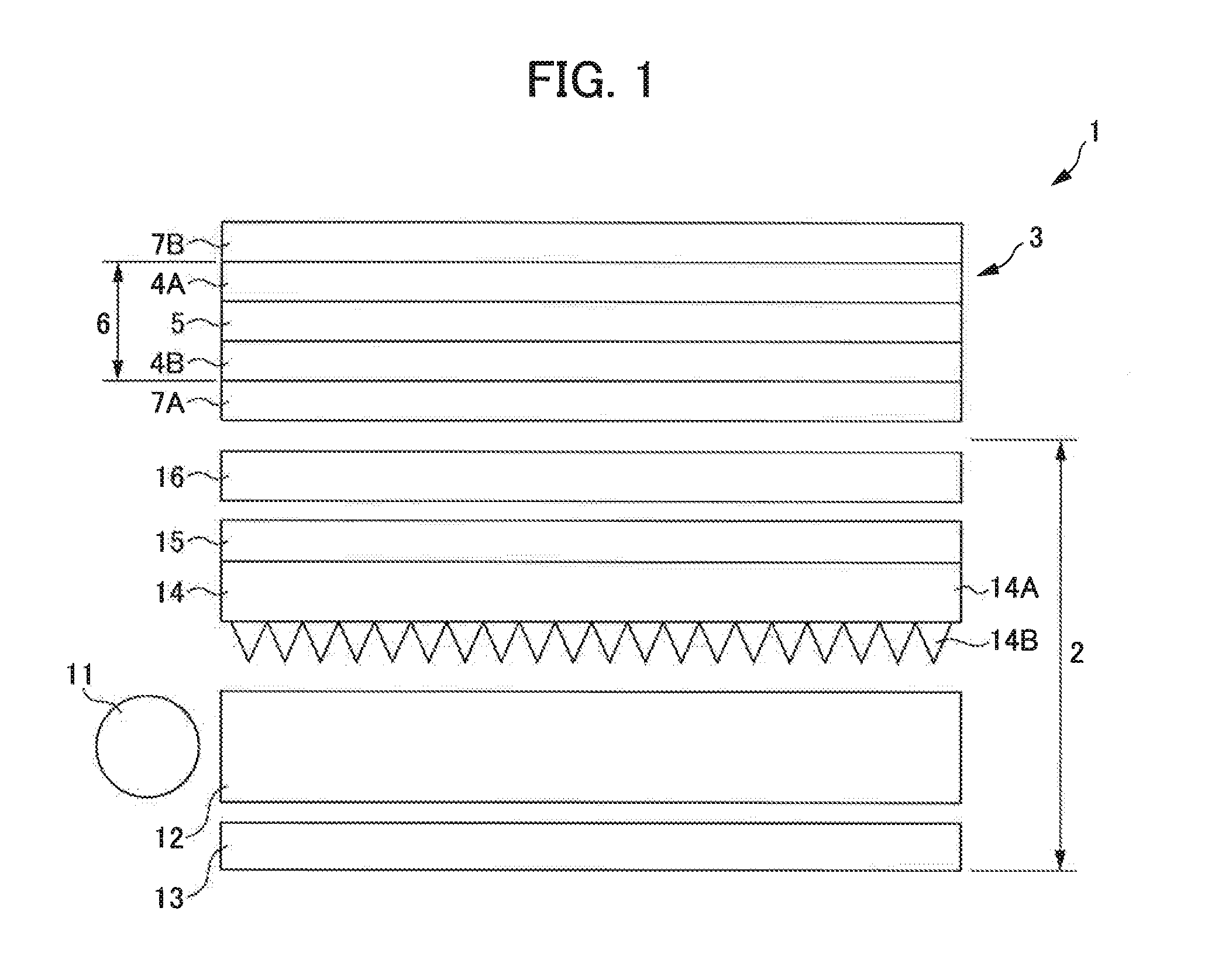
[0080]FIG. 1 is a cross-sectional view illustrating a schematic configuration of a liquid-crystal display apparatus according to a first embodiment of the present invention. This liquid-crystal display apparatus 1 is formed by stacking a backlight unit 2 and a liquid-crystal display panel 3. Here, the liquid-crystal display panel 3 has a configuration in which glass plates 4A and 4B having transparent electrodes formed therein sandwich a liquid crystal 5 to form a liquid crystal cell 6, and linear polarizing plates 7A and 7B are disposed on an incidence surface and an exit surface of the liquid crystal cell 6, respectively. With this configuration, the liquid-crystal display panel 3 modulates the intensity of the illumination light supplied from the backlight unit 2 according to driving of the transparent electrodes, outputs the modulated light, and displays a desired image. The liquid-crystal display panel may have a wide range of various types such as a twisted nematic (TN) type, ...

second embodiment

[0106]FIG. 3 is a diagram illustrating a liquid-crystal display apparatus according to a second embodiment of the present invention for comparison with FIG. 1. A liquid-crystal display apparatus 21 of the present embodiment has the same configuration as the liquid-crystal display apparatus 1 of the first embodiment except that a backlight unit 22 is disposed instead of the backlight unit 2. Moreover, the backlight unit 22 has the same configuration as the backlight unit 2 except that the ¼-wavelength plate 15 is disposed so as to be integrated with the reflective polarizing plate 16 instead of the prism sheet 14.

[0107]Here, with regard to the integration, the ¼-wavelength plate 15 may be provided so as to be integrated with the reflective polarizing plate 16 according to a transfer method. Alternatively, a retardation element associated with the ¼-wavelength plate 15 may be provided in the reflective polarizing plate 16. Further alternatively, the ¼-wavelength plate 15 may be attach...

third embodiment

[0111]FIG. 7 is a diagram illustrating a liquid-crystal display apparatus according to a third embodiment of the present invention for comparison with FIG. 1. A liquid-crystal display apparatus 31 of the present embodiment has the same configuration as the liquid-crystal display apparatus 1 of the first embodiment except that a backlight unit 32 is disposed instead of the backlight unit 2. Moreover, the backlight unit 32 has the same configuration as the backlight unit 2 except that the reflective polarizing plate 16 is disposed so as to be integrated with the prism sheet 14 and the ¼-wavelength plate 15.

[0112]Here, in integration of the prism sheet 14, the ¼-wavelength plate 15, and the reflective polarizing plate 16, similarly to that described in connection with the first embodiment, the reflective polarizing plate may be integrated using an adhesive such as an ultraviolet-curable resin after the prism sheet 14 and the ¼-wavelength plate 15 are integrated. Alternatively, similarl...


PUM

PropertyMeasurementUnit
apex angleaaaaaaaaaa
azimuthal angleaaaaaaaaaa
thicknessaaaaaaaaaa

Abstract

Sufficiently sharp directivity can be secured with a simple configuration in a configuration that improves the efficiency of utilizing the light exiting from a primary light source using a reflective polarizing plate. A backlight unit (2) supplies light exiting from an exit surface of a light guide plate (12) to a liquid-crystal display panel (3) via a reflective polarizing plate (16) after correcting directivity of the exiting light using a prism sheet (14) having a downwardly convex shape. A ¼-wavelength plate (15) is provided between the prism sheet (14) and the reflective polarizing plate (16), between the prism sheet (14) and the light guide plate, or between the light guide plate and a reflective sheet disposed on a surface of the light guide plate opposite to the prism sheet (14).

Description

[0001]This application is based on and claims the benefit of priority from Japanese Patent Application No. 2014-048872, filed on 12 Mar. 2014, and Japanese Patent Application No. 2014-115276, filed on 3 Jun. 2014, the content of which is incorporated herein by reference.BACKGROUND OF THE INVENTION[0002]1. Field of the Invention[0003]The present invention relates to a backlight unit, a liquid-crystal display apparatus, and a stacked structure, and specifically, relates to an edge-lit backlight unit in which light exiting from a primary light source, for example, enters a light guide plate from an edge (end surface) of the light guide plate and exits from an exit surface while propagating through the light guide plate and a liquid-crystal display apparatus which uses the edge-lit backlight unit.[0004]Moreover, the present invention relates to a liquid-crystal display apparatus which improves the efficiency of utilizing light exiting from a primary light source using a reflective polar...

Claims


Application Information

Patent Timeline
Patent Type & Authority Applications(United States)
IPC IPC(8): F21V8/00G02B5/04G02F1/1335G02B5/30G02F1/13363G02F1/1337
CPCG02B6/0056G02B6/0053G02B6/0055G02F1/13363G02F1/1337G02F2413/05G02B5/3083G02B5/3025G02B5/045G02F2001/133638G02F2413/01G02F1/133536
Inventor KASHIMA, KEIJISUZUURA, YASUKIYAMAMOTO, HIROSHIKURODA, TAKASHI
Owner DAI NIPPON PRINTING CO LTD
Why Eureka
Try Eureka