Optical pickup apparatus, objective optical element and optical information recording and/or reproducing apparatus

a pickup apparatus and optical information technology, applied in the field of optical pickup apparatus, objective optical element and optical information recording reproducing apparatus, can solve the problems of increasing cost, plurality of optical, and reducing light utilization efficiency, so as to improve light utilization efficiency, simplify the structure, and reduce the effect of cos

Inactive Publication Date: 2008-01-17
KONICA MINOLTA OPTO
View PDF6 Cites 26 Cited by
  • Summary
  • Abstract
  • Description
  • Claims
  • Application Information

AI Technical Summary

Benefits of technology

[0064]Further, the third light flux which passes through the first optical path difference providing structure of the objective optical element forms the first best focus where a spot diameter of the spot formed by the third light flux is the smallest and the second best focus where a spot diameter of the spot formed by is the second smallest to the first best focus. Incidentally, it is assumed that the best focus mentioned in this case means a point where beam-waist is minimum within a certain range of defocus. In other words, forming of the first best focus and the second best focus by the third light flux means that at least two points where the beam-waist is minimum within a certain range of defocus exist in the third light flux. Incidentally, it is preferable that, in the third light flux passing the first optical path providing structure, a diffracted light having the maximum light amount forms the first best focus, and a diffracted light having the second largest light amount forms the second best focus. Further, when the diffraction efficiency of a diffracted light forming the first best focus is greater than that of the diffracted light forming the second best focus, and when a difference between them is 15% or more (preferably, 30% or more), an effect of the invention that light utilization efficiency can be enhanced in the third light flux becomes more conspicuous.
[0065]It is preferable that a spot formed by the third light flux at the first best focus is used for recording and / or reproducing for the third optical disk and a spot formed by the third light flux at the second best focus is not used for recording and / or reproducing for the third optical disk. However, an embodiment wherein a spot formed by the third light flux at the first best focus is not used for recording and / or reproducing for the third optical disk and a spot formed by the third light flux at the second best focus is used for recording and / or reproducing for the third optical disk, is not denied. Meanwhile, when the first optical path difference providing structure is provided on the surface of the objective optical element facing a light source, there are considered two cases including one occasion where the second best focus is closer to the objective optical element than the first best focus is and another occasion where the second best focus is farther from the objective optical element than the first best focus is. For example, when a zero-th order diffracted light of the third light flux forms the second best focus, a position of the second best focus is closer to the objective optical element than that of the first best focus formed by the first order diffracted light of the third light flux. On the other hand, when the second best focus is formed by the second order diffracted light of the third light flux, a position of the second best focus is farther from the objective optical element than that of the first best focus formed by the first order diffracted light of the third light flux.
[0066]Further, the first best focus and the second best focus satisfy the following expression (1):0<L / f<0.05   (1)Where, f [mm] represents a focal length of the third light flux that passes through the first optical path difference providing structure and forms the first best focus, while, L [mm] represents a distance between the first best focus and the second best focus.
[0067]Incidentally, it is more preferable to satisfy the following expression (1′).0.01≦L / f≦0.043   (1′)
[0068]More preferable is to satisfy the following expression (1″).0.016≦L / f≦0.042   (1″)
[0069]Further, L is preferably 0.03 mm or more, and 0.11 mm or less, and f is preferably 1.8 mm or more, and 3.0 mm or less.

Problems solved by technology

On the other hand, it is sometimes considered that a product, such as an optical disk player / recorder, which is capable of only recording / reproducing information for the above high-density optical disk is worthless.
However, it requires a plurality of optical systems, which is disadvantageous for the size-reduction and which increases the cost.
However, the objective optical element for use in the optical pickup apparatus which compatibly conducts recording and / or reproducing information for three different optical disks, which is written in EP-A 1304689, has a probability that the light amount used for recording and / or reproducing information is insufficient, and that proper flare is hardly generated when information is recorded and / or reproduced for CD or DVD, depending on the design specification of the optical pickup apparatus, which are problems.

Method used


Image

  • Optical pickup apparatus, objective optical element and optical information recording and/or reproducing apparatus
  • Optical pickup apparatus, objective optical element and optical information recording and/or reproducing apparatus
  • Optical pickup apparatus, objective optical element and optical information recording and/or reproducing apparatus

Examples


example 1

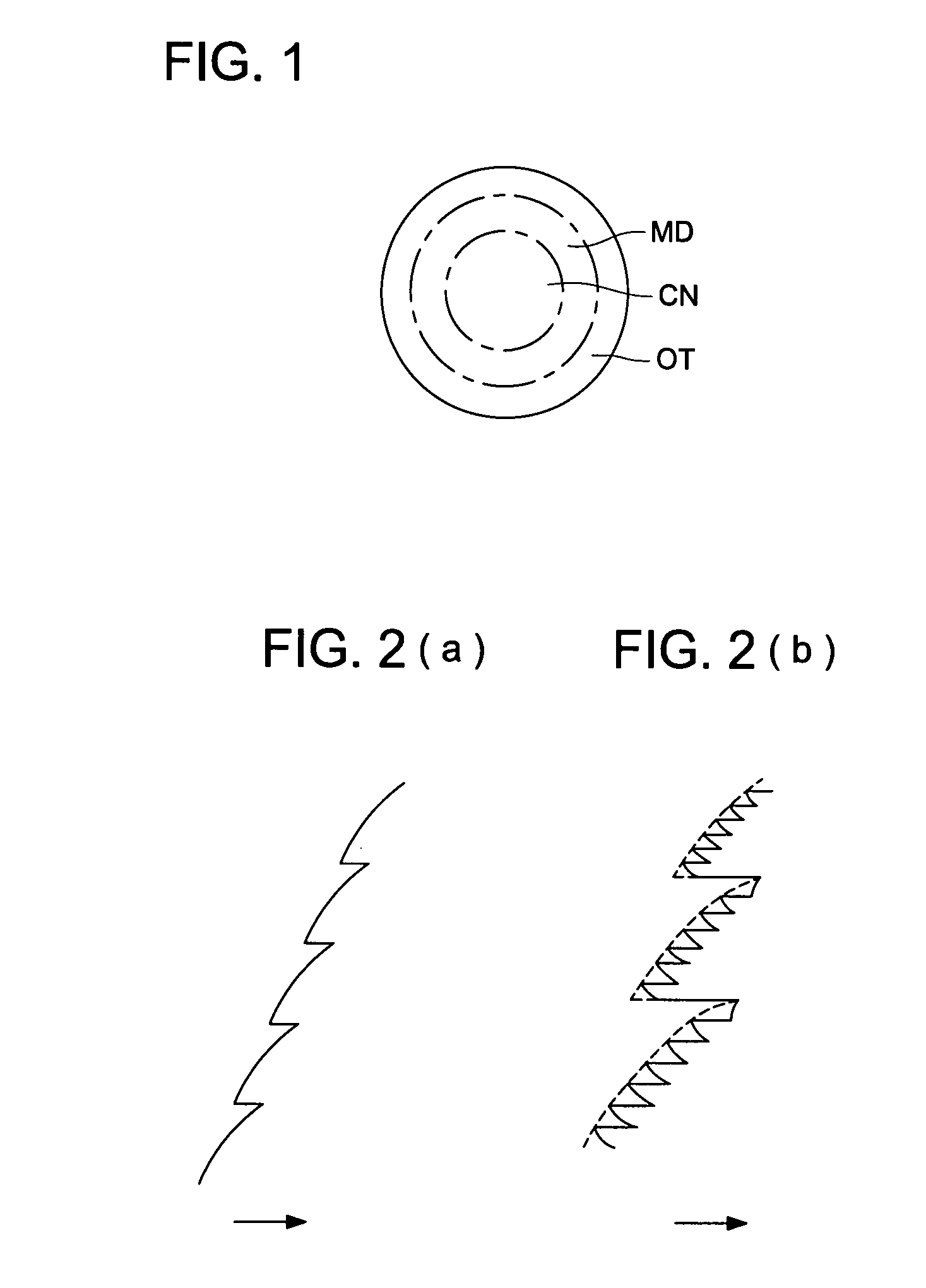
[0157]Next, an example that can be used in the aforesaid embodiment will be explained. In the following examples, the objective optical element is a single lens made of polyolefin-based plastic. On the entire surface of central area CN on the optical surface of the objective optical element, there is formed the first optical path difference providing structure. On the entire surface of peripheral area MD on the optical surface, there is formed the second optical path difference providing structure. On the entire surface of most peripheral area OT on the optical surface, there is formed the third optical path difference providing structure.

[0158]Further, in Example 1, the first optical path difference providing structure is of the structure comprising only the first basic structure, which is in a serrated form as shown schematically in FIG. 2(a). The first basic structure representing a diffractive structure in a serrated form is designed to make a diffracted light amount of the firs...

example 2

[0169]Example 2 will be described as follows.

[0170]Lens data of Example 2 are shown in Table 2 below. Each of FIGS. 7(a), 7(b) and 7(c) shows a vertical spherical aberration diagram in Example 2. The numeral 1.0 on the vertical axis in the vertical spherical aberration diagram represents NA 0.85 or a diameter of 3.74 mm. Incidentally, L=0.098 mm and f=2.334 mm hold in Example 2. Therefore, L / f=0.098 / 2.334=0.042 holds. Further, in Example 2, when a wavelength of a light flux for BD is changed by +5 nm, an amount of change of the third order spherical aberration is −0.188 λ rms, an amount of change of the fifth order spherical aberration is −0.021 λ rms, an amount of change of the seventh order spherical aberration of is 0.030 λ rms, and an amount of change of the ninth order spherical aberration is −0.016 λ rms. Therefore, the total amount of change of the third to ninth order spherical aberrations of is 0.192 λ rms. Further, in Example 2, when a wavelength of the light flux for BD i...

example 3

[0172]Example 3 will be described as follows. Example 3 differs from Example 1 in the point that the seventh basic structure is overlapped to a part (a region closer to the most peripheral area) of the peripheral area and a part (a region closer to the peripheral area) of the most peripheral area of the objective optical element in order to outreach the third light flux as a flare as far as possible. In other words, there can be given the second optical path difference providing structure whose inside area closer to an optical axis has the structure in which the second basic structure and the third basic structure are overlapped to each other, and whose outside area farther than the inside area from the optical axis has the structure in which the second basic structure, the third basic structure, and the seventh basic structure are overlapped to each other. Further there can be given the third optical path difference providing structure divided into an inner side area closer to an o...


PUM

PropertyMeasurementUnit
refractive indexaaaaaaaaaa
wavelengthaaaaaaaaaa
diameteraaaaaaaaaa

Abstract

An optical pickup apparatus comprises: a first light source for emitting a first light flux; a second light source for emitting a second light flux; a third light source for emitting a third light flux; and an objective optical element. The objective optical element comprises an optical surface comprising a central area and a peripheral area. The central area comprises a first optical path difference providing structure, and the peripheral area comprises a second optical path difference providing structure. The objective optical element converges the third light flux which passes through the central area of on the third optical disk. The objective optical element converges the first and second light fluxes which pass through the peripheral area on the first optical disk. Each of the first and second optical path difference providing structures comprises a predetermined basic structure.

Description

[0001]This application is based on Japanese Patent Application Nos. 2006-193769 filed on Jul. 14, 2006, and 2006-285298 filed on Oct. 19, 2006 in Japanese Patent Office, the entire content of which is hereby incorporated by reference.BACKGROUND OF THE INVENTION[0002]The present invention relates to an optical pickup apparatus, objective optical element and optical information recording reproducing apparatus by which information can be recorded and / or reproduced information compatibly for different kinds of optical disks.[0003]In recent years, tendency of a shorter wavelength of laser beam as a light source which has been used to record and / or reproduce information for optical disks, has become a main stream. For example, a laser light source having 400-420 nm wavelength, such as a blue-violet semiconductor laser; and a blue-SHG laser which converts wavelength of an infrared semiconductor laser utilizing a second harmonic wave, have been made practical. Information of 15-20 GB can be...

Claims


Application Information

Patent Timeline
Patent Type & Authority Applications(United States)
IPC IPC(8): G11B7/00
CPCG11B7/1353G11B2007/0006G11B7/13922G11B7/1374G02B5/18G02B13/00
Inventor NOMURA, EIJINAKAMURA, KENTAROU
Owner KONICA MINOLTA OPTO
Why Eureka
Try Eureka