Measuring device

a measuring device and a technology of a measuring device, applied in the direction of optical radiation measurement, instruments, magnetic property measurement, etc., can solve the problems of spatial resolution degrade spatial resolution degrade, etc., and achieve the effect of simple structure and high spatial resolution

Inactive Publication Date: 2006-03-30
FUJITSU LTD
View PDF1 Cites 26 Cited by
  • Summary
  • Abstract
  • Description
  • Claims
  • Application Information

AI Technical Summary

Benefits of technology

[0026] It is an object of the present invention to provide a measuring device of high spatial resolution and a high S / N having simple structure and capable of measuring in-plane magnetization and / or magnetic field vector components, or capable of measuring in-plane magnetization and / or magnetic field vector components separately from perpendicular magnetization and / or magnetic field vector component.

Problems solved by technology

In the method of deviating intensity distribution of the light incident on the object lens pupil, for example, the method in which the light is made incident on the half of the pupil with its light incident angle being deviated from the perpendicular direction to the surface of the magnetic substance, of the object lens pupil to detect the polarization state so that the in-plane magnetization vector components are measured using the longitudinal Kerr effect and the transverse Kerr effect, there is a disadvantage that the polar Kerr effect by the perpendicular magnetization vector component is also detected at the same time.
Further, it is easy to make a light beam having the diameter approximately half of that of the pupil incident on the half of the pupil in order to efficiently use the light from the light source but, in this case, spatial resolution is degraded because actually-used effective numerical aperture NA among the NA of the object lens becomes substantially small.
If the light beam from the light source having the diameter approximately the same or larger than the diameter of the object lens pupil is made incident on the object lens with a half thereof being shielded, the effective NA can be made somewhat larger than in the aforesaid method, but there still exists a problem that spatial resolution is degraded and light usage efficiency also considerably lowers.
In this case, since the two light sources operate incoherently and independently, an obtained light intensity focusing spot becomes a spot resulting from overlaying light intensity focusing spots which are independently formed by the respective two light sources, which reduces the effective NA similarly to the above description and lowers focusing performance.
In addition, since the two independent light sources and polarization detectors are used, the structure is complicated and not easy to adjust.
Since the magnetic Kerr effect is feeble, a fine signal buried in circuit noise or other noise needs to be extracted by signal processing, and a problem that measurement accuracy directly lowers arises if noise is thus increased.
Furthermore, the light incident position on the two-divided or four-divided photo-detector needs to be precisely adjusted so that a divisional detection ratio of the light becomes a predetermined ratio, that is, the light is equally distributed to each divided part in general, and this adjustment becomes difficult if an element having a small light receiving area is used.
Moreover, in the case of a differential polarization detecting optical system in which two of the divided photo-detectors are used and two orthogonal polarization components are detected to obtain difference therebetween, light amount noise is canceled and a high S / N is easily obtained but, in this case, light incident positions on the two divided detectors have to be adjusted at the same time, which becomes more difficult.
Meanwhile, in the case of a photo-detector having a large light receiving area, since junction capacitance of the detector becomes large and high-speed response is not easily obtained as well as it is difficult to realize an I / V amplifier capable of giving the high-speed response while having large input capacitance, a problem that a high-speed light receiving and detection system cannot be formed arises.
In addition, it is also difficult to realize an add-subtract circuit which accurately operates at a high frequency.
Therefore, the method of using the divided photo-detector can be applied to a scanning-type laser microscope using a point light source, but it is impossible to simultaneously irradiate the light from the light source to a certain region of the sample, focus the reflected light by an imaging lens, and receive its image by a CCD camera so as to observe in-plane magnetized distribution in an image.
Furthermore, visual observation through an eyepiece lens is also impossible.
Further, a complicated mechanism becomes necessary to make orientation of the photo-detector rotatable in order to freely rotate the axes.

Method used


Image

  • Measuring device
  • Measuring device
  • Measuring device

Examples


third embodiment

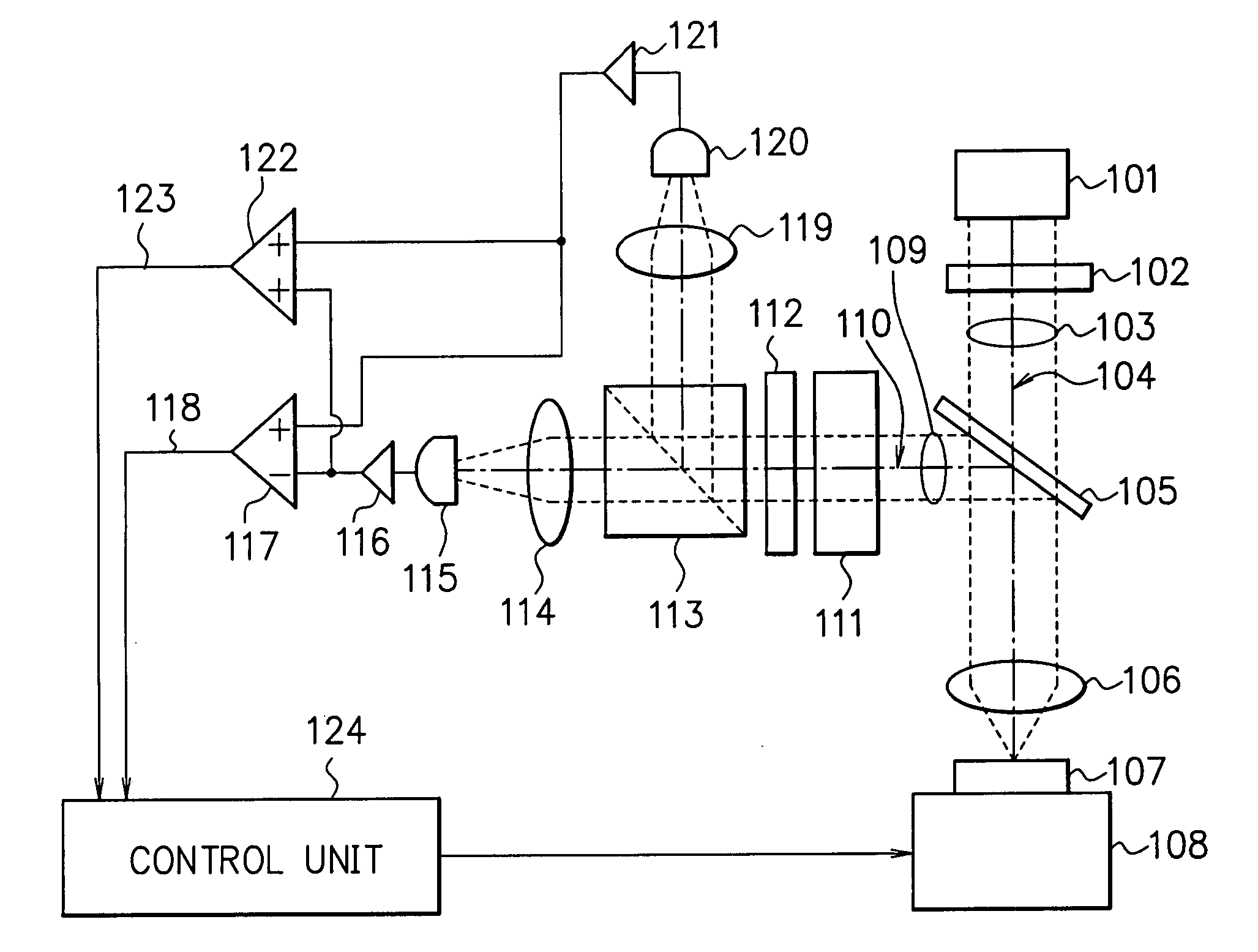
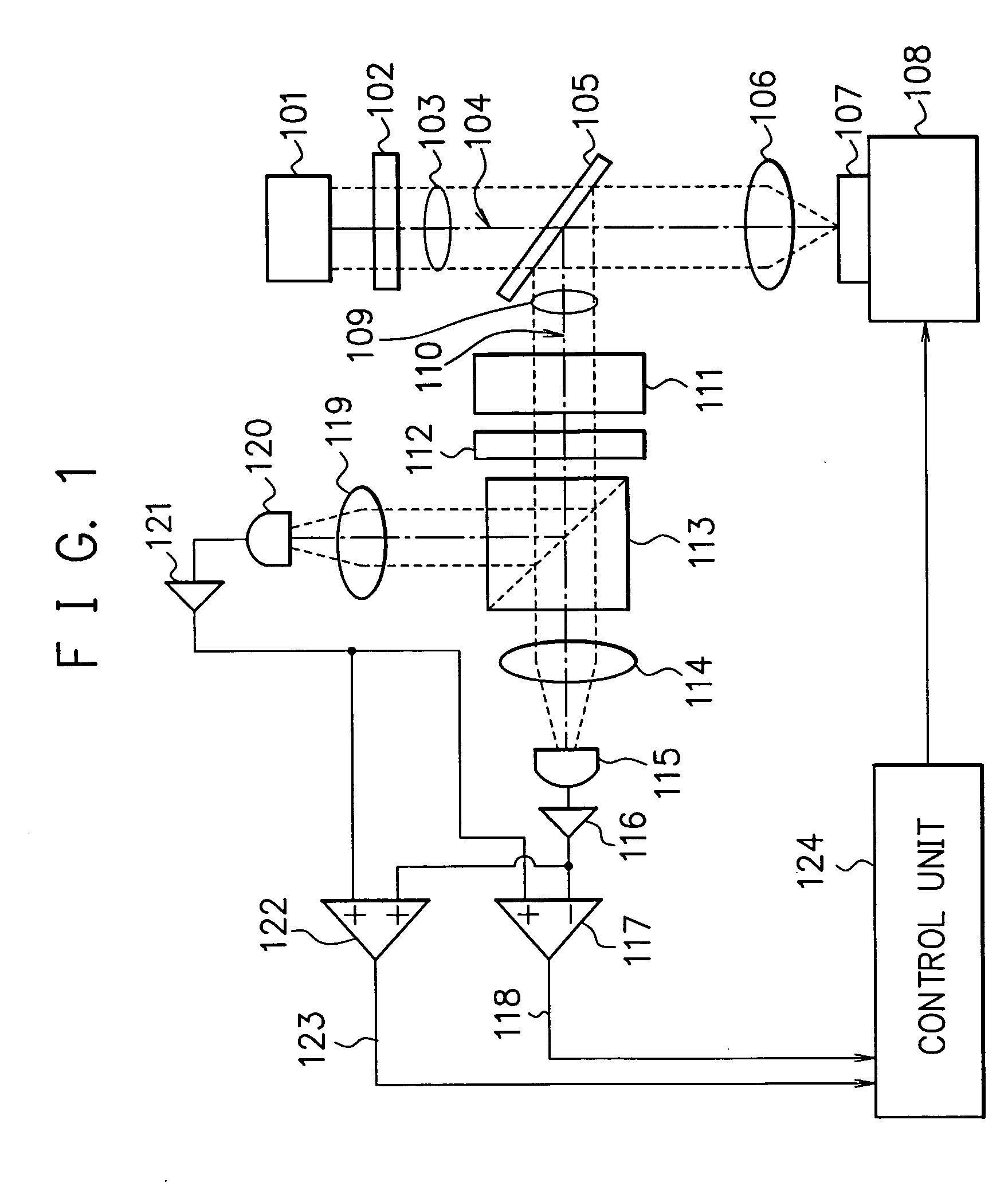
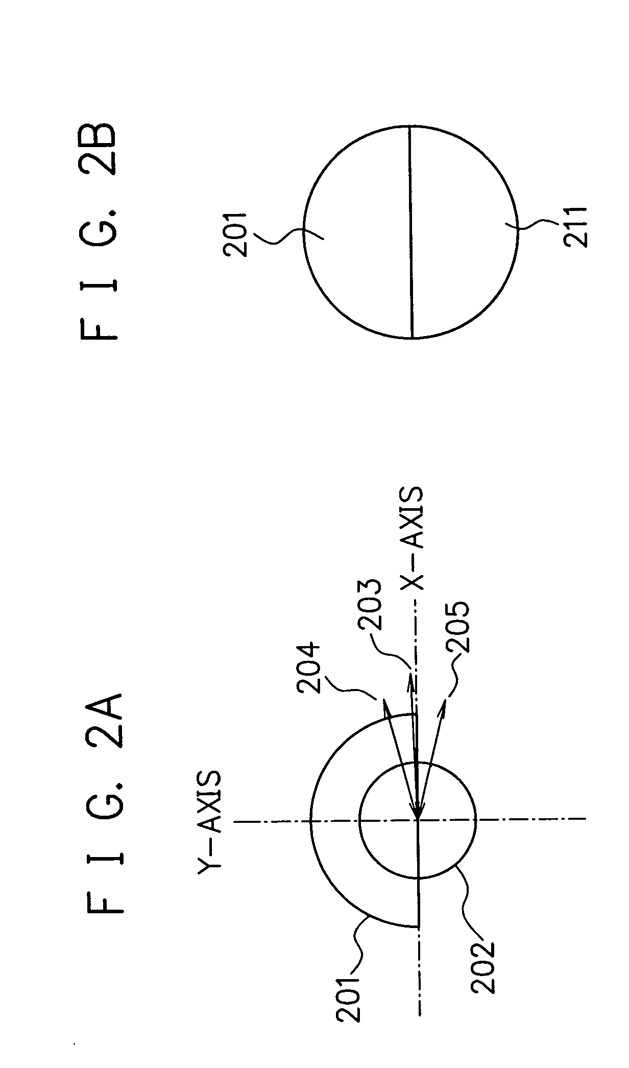
[0113]FIGS. 3A and 3B show examples of a divisional polarization rotation element as a typical example of the half-turn asymmetric polarizing element 111 (FIG. 1) according to a third embodiment of the present invention. The example of FIG. 3A shows a divisional optically active element 301 constituted of a semicircular optically active plate as the divisional polarization rotation element. The optically active element 301 can be made of optically active crystals such as quartz. This semicircular divisional optically active element 301 has action which gives +90-degree (π / 2 radian) rotation 303 to polarization of the passing light. It is supposed that the light source 101 outputs linearly polarized light and a cross section of a light beam 302 has a circular shape and intensity distribution axially symmetric with respect to the optical axis, but the intensity distribution may have an elliptic shape whose principal axes are in the X- and Y-axis directions. An upper half of the light ...

fourth embodiment

[0131]FIG. 4 shows an example of a divisional half-wave element as a typical example of the half-turn asymmetric reflectional symmetry polarizing element 111 (FIG. 1) according to a fourth embodiment of the present invention. In this example, an azimuth angle of a neutral axis 411 of an upper-half first divisional half-wave plate 401 is set to θ1=π / 8 radian, and an azimuth angle of a neutral axis 421 of a lower-half second divisional half-wave plate 402 is set to θ2=−π / 8 radian. The output light flux from the light source is the linearly polarized light and it has half-turn symmetry nature around the optical axis of the optical system and reflectional symmetry nature with respect to a plane including the optical axis and a polarization azimuth. The polarization azimuth is defined as the X-axis and a polarization azimuth angle incident on the divisional half-wave plates in a state in which there is no Kerr effect is defined as 0 radian.

[0132] It is supposed that the polarization spl...

fifth embodiment

[0153]FIG. 5 shows an example of a divisional ¼ wave element as a typical example of the half-turn asymmetric reflectional symmetry polarizing element 111 (FIG. 1) according to a fifth embodiment of the present invention. In this example, an azimuth angle of a neutral axis (either a slow axis or a fast axis) 511 of an upper-half first divisional quarter-wave plate 501 is θ1=π / 4 radian, and an azimuth angle of a neutral axis 521 of a lower-half second divisional quarter-wave plate 502 is θ2=−π / 4 radian. A polarization azimuth angle of the linearly polarized light incident on the divisional quarter-wave plates 501, 502 in the state without the Kerr effect is 0 radian.

[0154] Differential polarization is detected by setting the polarization split direction of the polarization split detector to the X- and the Y-axis direction. When the case where the linearly polarized light received the Kerr rotation of +δ radian is incident is considered, the light passed through the first and second ...


PUM

PropertyMeasurementUnit
anglesaaaaaaaaaa
anglesaaaaaaaaaa
azimuth angleaaaaaaaaaa

Abstract

Provided is a measuring device which has a focusing unit for focusing light flux from a light source and irradiating it to a magnetic substance to be measured, a half-turn asymmetric element acting only on the light flux reflected by the magnetic substance to be measured and acting in such a manner that its action on polarization distribution in a cross section of the light flux has asymmetry nature about half-turn around an optical axis in order to obtain sensitivity to in-plane magnetization vector components of the magnetic substance to be measured, and a polarization split detector for detecting a light amount of a polarization component in one direction or separated each component of polarization components orthogonal to each other of the light which receives action of the half-turn asymmetric element so that the in-plane magnetization vector component in one direction can be measured separately from other components.

Description

CROSS-REFERENCE TO RELATED APPLICATIONS [0001] This application is based upon and claims the benefit of priority from the prior Japanese Patent Application No. 2002-253539, filed on Aug. 30, 2002, the entire contents of which are incorporated herein by reference. BACKGROUND OF THE INVENTION [0002] 1. Field of the Invention [0003] The present invention relates to a measuring device, and particularly to a measuring device for detecting magneto-optical effects such as a magnetic Kerr effect and a Faraday effect. [0004] 2. Description of the Related Art [0005] In order to measure a magnetization state of a magnetic substance, a method of irradiating light to the magnetic substance and detecting change in polarization state and reflectivity of the reflected light due to a magnetic Kerr effect is widely being used. For example, with a device called a Kerr effect measuring device, a Kerr effect magnetic domain observing device, and the like, M-H characteristics can be measured and magnetic...

Claims


Application Information

Patent Timeline
Patent Type & Authority Applications(United States)
IPC IPC(8): G02F1/01G01R33/032G01R33/12
CPCG01R33/032
Inventor NAGAI, TOSHIAKI
Owner FUJITSU LTD
Why Eureka
Try Eureka