Method and apparatus for forming an image that shows information about a subject

a technology of information and subject, applied in the field of method and apparatus for forming an image that shows information about a subject, can solve the problems of affecting the operation of the subject, and introducing the possibility of biohazard contamination to the subject and the operator, and achieves high contrast resolution, high spatial resolution, and easy operation.

Inactive Publication Date: 2005-12-27
TOSHIBA MEDICAL SYST CORP
View PDF6 Cites 121 Cited by
  • Summary
  • Abstract
  • Description
  • Claims
  • Application Information

AI Technical Summary

Benefits of technology

[0024]The present invention has been made in view of the foregoing. An object of the invention is to provide an apparatus for forming an image that provides information about a subject being examined. The apparatus has a data acquisition system easy to operate to form an image showing information about the subject, by using the photoacoustic effect inside the living body, and which can generate data representing an image having high contrast resolution and high spatial resolution.
[0026]The present invention provides a method for the determination of the distribution of a substance in human tissue and superimposing this distribution on a morphological image on the body part under examination to yield better diagnosis. The method utilized common body interface and common detectors, with the light sources interposed between the detectors in one structure. Same pressure applies, same air gaps, same interfaces to minimize image distortion.
[0027]The present invention also provides an apparatus that can display a photoacoustic image and ultrasound image of almost the same region of a tissue being examined, and is very easy to operate because the same photoacoustic detectors used are sound conversion elements, which can receive photo-generated acoustic waves, can also transmit and receive ultrasonic waves.

Problems solved by technology

The extraction of the fluid is painful.
It damages the skin of the subject and introduces the possibility of biohazard contamination to the subject and the operator.
Breast cancer is a major source of mortality in females.
These set of steps take considerable time before reaching a final conclusion.
These methods suffer from imprecision of image conversion and image distortions close to the edges of the body part, such as the breast.
Further, MRI and CAT scan have large expensive equipment that cannot be transformed easily.
They do not teach combination of photoacoustic and ultrasound images that are detected using co-registered ultrasound transducers.
The method leads to the possibility of distortion of the vascular image due to effect of the morphological features on tissue bulk modulus.
Does not teach combination of photoacoustic and ultrasound images that are detected using co-registered ultrasound transducers.
However, none of these publications teaches techniques of providing an image showing concentration distributions.
Therefore, when the photoacoustic imaging method is performed to examine the breast for cancer as described in A. Oraevsky et al., “Laser optoacoustic imaging of breast cancer”, it is difficult to determine an accurate positional relationship between a tumor and morphological features in the tissue and such as healthy mammary gland tissue surrounding it.

Method used


Image

  • Method and apparatus for forming an image that shows information about a subject
  • Method and apparatus for forming an image that shows information about a subject
  • Method and apparatus for forming an image that shows information about a subject

Examples


first embodiment

[0071]The first embodiment of the present invention will be described, with reference to FIGS. 1 to 6.

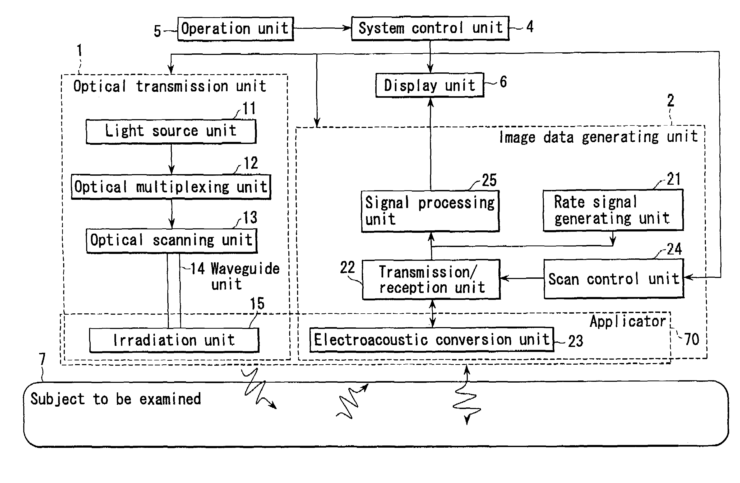
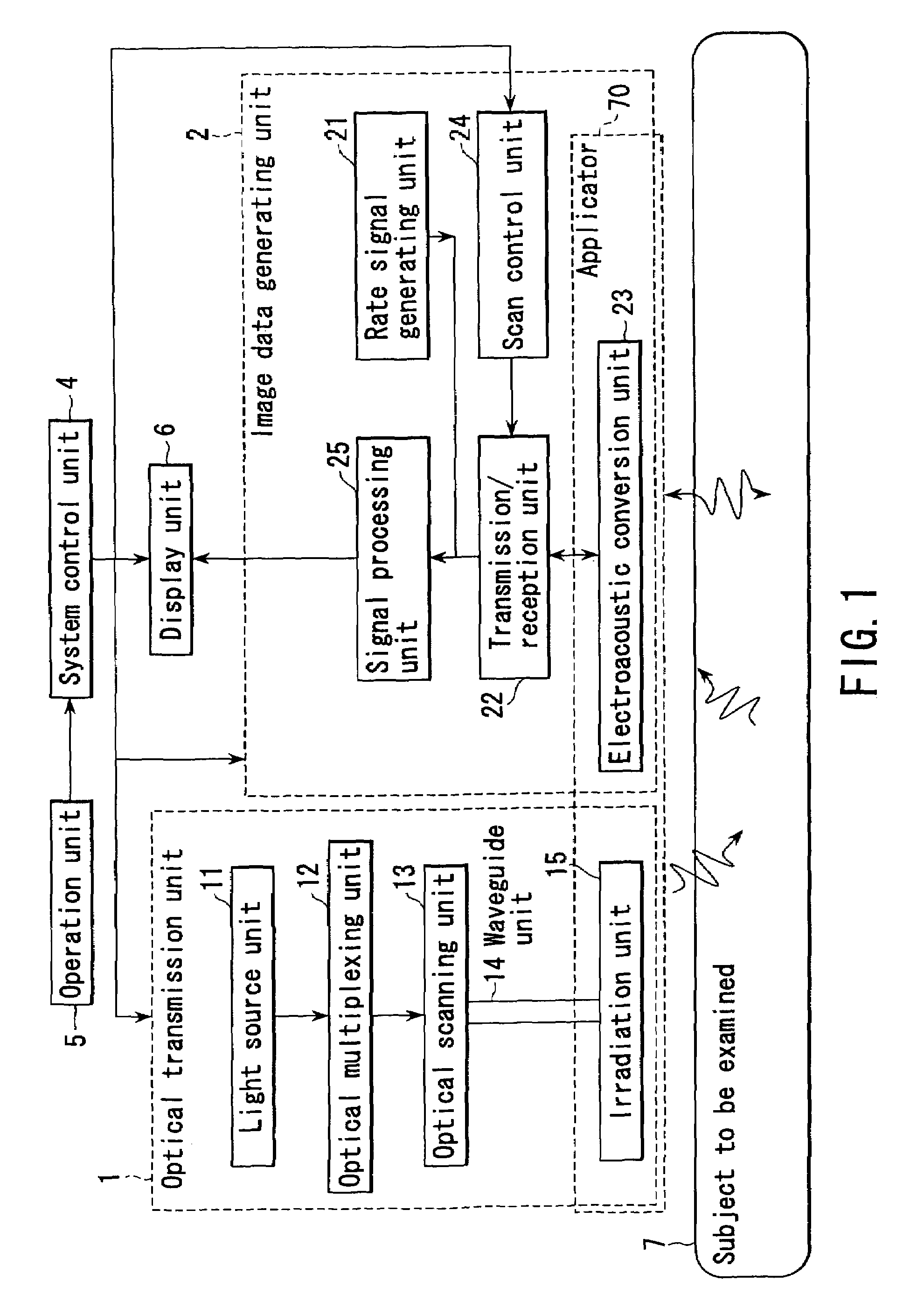
[0072]The first embodiment is a subject-information imaging apparatus that can form an image showing a hemoglobin distribution in the subject, which will be used to diagnose breast cancer. The apparatus is characterized in that the electroacoustic conversion unit is integrally formed with the irradiation unit. That is, the optical fibers of the irradiation unit have their output ends held between the electroacoustic transducer elements arrayed in the electroacoustic conversion unit. The apparatus can perform a photoacoustic imaging method and a conventional pulse echo method, by using this electroacoustic conversion unit, to combine and display the image data items obtained from the same region in the subject.

[0073]Hereinafter, the sound waves generated by the photoacoustic imaging method will be referred to as “acoustic waves” and the sound waves transmitted / received by the general...

second embodiment

[0130]The second embodiment of the present invention will be described with reference to FIGS. 7A to 7C. In the second embodiment, the harmonic imaging method acquires ultrasonic image data. The method of acquiring photoacoustic image data and the method of transmitting ultrasonic waves in the pulse echo method, both performed in this embodiment, are identical to those used in the first embodiment. Therefore, they will not be described.

[0131]In the photoacoustic imaging method, the frequency spectrum of an acoustic wave ranges from 200 kHz to 2 MHz, with 1 MHz being the center frequency. The conversion elements 54 of the electroacoustic conversion unit 23 must have properties that correspond to such frequency components. The center frequency is lower than the center frequency (for example, fo: 3.5 MHz) that is applied in standard pulse echo methods.

[0132]In the first embodiment, the same conversion elements 54 acquire both the photoacoustic image data and the ultrasonic image data. ...

third embodiment

[0140]The third embodiment of this invention is a simplified reception method that may be employed in photoacoustic imaging. This reception method will be described with reference to FIG. 8. The method of acquiring ultrasonic image data and the method of irradiating a subject, both performed in the photoacoustic imaging method in this embodiment, are identical to those employed in the first embodiment. They will not be described.

[0141]FIG. 8 shows the position where irradiation light is applied and the positions where acoustic waves are applied, in the third embodiment. The subject 7 is irradiated with light applied through an optical fiber 71-1 as shown in FIG. 8. The light travels straight, while maintaining its small diameter. That is, it exhibits good directivity. Therefore, a photoacoustic image can be generated without performing phased addition processing at the time of reception of acoustic waves.

[0142]In the first scan in photoacoustic imaging, the subject 7 is irradiated w...


PUM

PropertyMeasurementUnit
wavelengthsaaaaaaaaaa
emission wavelengthaaaaaaaaaa

Abstract

An apparatus includes an optical transmission unit which irradiates a subject to be examined with light containing a specific wavelength component, an electroacoustic conversion unit which receives acoustic waves generated inside the subject by the light radiated by the optical transmission unit and converts them into electrical signals, an image data generating unit which generates first image data on the basis of the reception signals obtained by the electroacoustic conversion unit, an electroacoustic conversion unit which receives ultrasonic reflection signals obtained by transmitting ultrasonic waves to the subject and converts them into electrical signals, an image data generating unit which generates second image data on the basis of the reception signals obtained by the electroacoustic conversion unit, and a display unit which combines the first and second image data and displays the resultant data.

Description

CROSS-REFERENCE TO RELATED APPLICATIONS[0001]This application is based upon and claims the benefit of priority from the prior Japanese Patent Application No. 2003-190336, filed Jul. 2, 2003, the entire contents of which are incorporated herein by reference.BACKGROUND OF THE INVENTION[0002]1. Field of the Invention[0003]The present invention relates to a method and apparatus for aquiring and superimposing two acoustic images, one generated from the energy of light radiated into a subject being examined and the second is an ultrasound echo image generated from ultrasonic waves directed into the subject being examined superposition of the two images yields a distribution of substance concentration with respect to morphological features in the subject's tissue.[0004]2. Description of the Related Art[0005]A method of acquiring information about a subject has been used to measure the concentration of a component contained in a body fluid such as blood, other body fluids in the subject or ...

Claims


Application Information

Patent Timeline
Patent Type & Authority Patents(United States)
IPC IPC(8): A61B8/00A61B5/00A61B8/08G01N21/17G01N21/25G01N29/06G01N29/12G01N29/46
CPCA61B5/0091A61B5/0095A61B5/4312G01N21/1702G01N21/255G01N29/0609G01N29/0672G01N29/12G01N29/46A61B8/0825G01N2021/1787G01N2201/0826G01N2291/02475G01N2291/0258G01N2291/02809A61B5/7232A61B5/0062A61B8/4416A61B8/5261A61B8/08
Inventor KANAYAMA, SHOICHIITSUMI, KAZUHIRO
Owner TOSHIBA MEDICAL SYST CORP
Why Eureka
Try Eureka