Apparatus and method for efficiently increasing the spatial resolution of images

Inactive Publication Date: 2005-08-30
LOCKHEED MARTIN CORP
View PDF16 Cites 127 Cited by
  • Summary
  • Abstract
  • Description
  • Claims
  • Application Information

AI Technical Summary

Benefits of technology

[0010]According to one embodiment of the present invention, a method has been found that effectively and efficiently increases the apparent spatial resolution of a source image based on an auxiliary, co-registered image of a higher spatial resolution. In what follows, an image is a collection of pixels. A pixel is the smallest unit of spatial subdivision

Problems solved by technology

However, sensors or film used in cameras or scanners that acquire multi-spectral images are more complex and expensive than sensors or film used to acquire single spectral band images.
The cost of cameras and sensors to acquire high quality multi-spectral images at high resolutions may be extremely expensive.
Specifically, the technique discl

Method used


Image

  • Apparatus and method for efficiently increasing the spatial resolution of images
  • Apparatus and method for efficiently increasing the spatial resolution of images
  • Apparatus and method for efficiently increasing the spatial resolution of images

Examples


example 1

[0034]Source Image: 200×200 pixels[0035]Auxiliary Image: 400×400 pixels from panchromatic sensor[0036]Multiple: (2× in each linear dimension)[0037]Common Resolution: 200×200

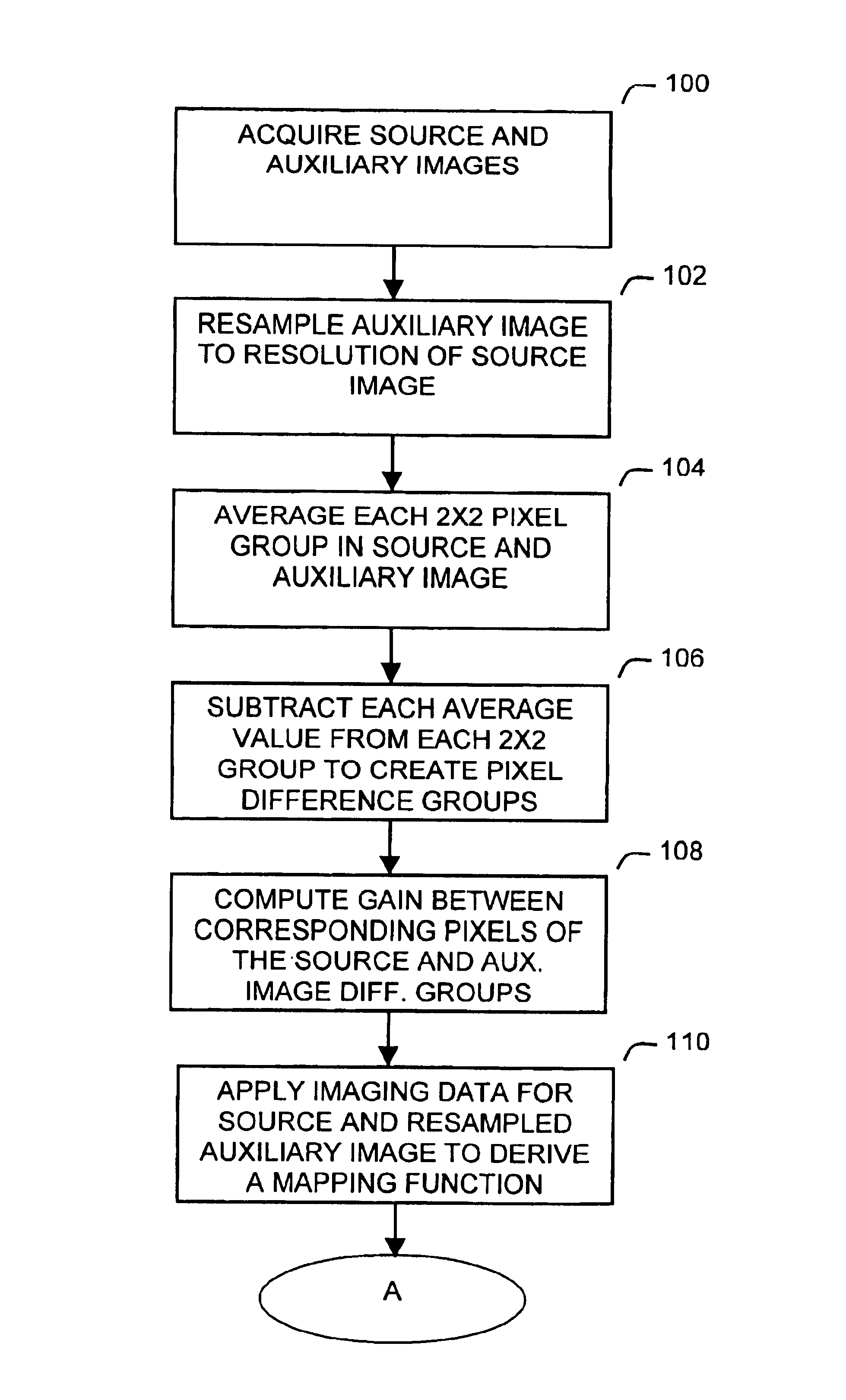
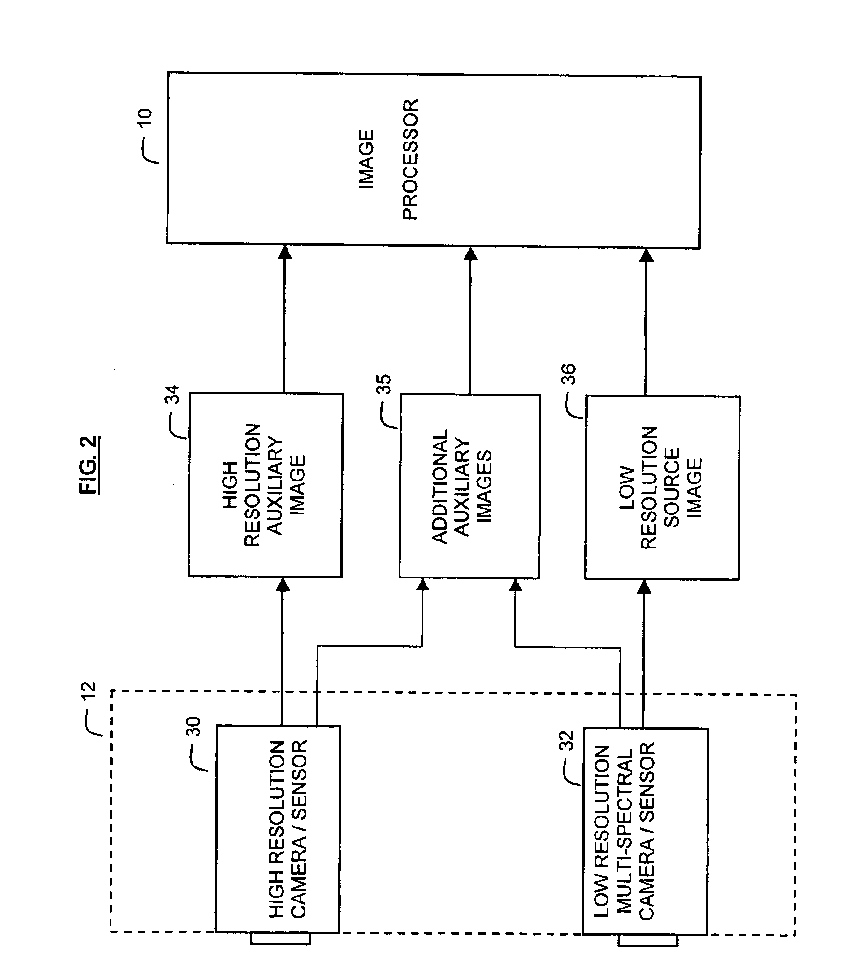
[0038]To resample the 400×400 pixel auxiliary image, define groups 50 of pixels in the auxiliary image as 2×2 groups of high-resolution pixels 52. Take the average pixel intensity value of each group 50 and define a new, coarse pixel 55 representing each group in the re-sampled 200×200 pixel auxiliary image. There is no need to resample the source image because the re-sampled auxiliary image has been converted to the same spatial resolution as the source image.

example 2

[0039]Source Image: 300×300 pixels[0040]Auxiliary Image: 800×800 pixels from panchromatic sensor[0041]Multiple: (2.66× in each linear dimension)[0042]Common Resolution: 300×300 pixels

[0043]Because the spatial resolution of the auxiliary image is not an integer multiple of the spatial resolution of the source image, the auxiliary image is resampled twice. First, the auxiliary image 34 is resampled to an intermediate spatial resolution of 600×600 pixels. This resampling is done by converting each 1.33 pixels in the 800×800 pixel auxiliary image 34 to 1 pixel using pixel interpolation. Subsequently, the intermediate auxiliary image is resampled a second time by grouping high resolution pixels 52 in the auxiliary image into 2×2 groups 50. The average pixel intensity value of each 2×2 group 50 defines a new, coarse pixel 55 representing each group in the 300×300 pixel resampled auxiliary image 38. There is no need to resample the source image 36 because the resampled auxiliary image 38 i...


PUM


Abstract

A method increases the spatial resolution of a source image based on an auxiliary, co-registered image of a higher spatial resolution. Each of the source and auxiliary images includes a plurality of pixels with corresponding spectral intensities and the method includes reducing, identifying, deriving, subdividing and modifying steps. Multiple auxiliary images can be used with the method.
In the reducing step, a spatial resolution of the auxiliary image is reduced to a common resolution with the source image. Then in the identifying step, corresponding groups of pixels at the common resolution in the source and auxiliary images are identified. Then in the deriving step, a mapping function is derived which relates the rate of change of intensity of each group in the auxiliary image and the corresponding rate of change of intensity in the corresponding group in the source image to the intensity vector. This map can be conditioned on any number of auxiliary image planes.
In the subdividing step, each source pixel is subdivided. Then in the modifying step, the spectral intensity of each subdivided source pixel is modifying based on the map and the local intensity variations of the auxiliary image. This results in increasing the resolution of the source image.

Description

FIELD OF THE INVENTION[0001]The present invention relates generally to image processing and more particularly to techniques for enhancing the spatial sharpness or resolution of an image using a higher resolution, substantially co-registered image.BACKGROUND OF THE INVENTION[0002]Image processing refers to any and all activities that acquire, manipulate, store and display images. Many specific useful applications arise in, for example, photography, medical imaging and satellite imaging.[0003]Images are typically acquired with a camera or scanner that exposes sensors or film that register a single spectral band or multiple spectral bands of incident radiation from a scene to be imaged. Monochrome images are examples of images acquired using a single spectral band. Color images are examples of images acquired using several spectral bands that represent blue, green, and red signals. In general, multi-spectral images contain more useful information than single spectral band images. Howev...

Claims


Application Information

Patent Timeline
IPC IPC(8): G06T3/40
CPCG06T3/4061
Inventor SPECHT, DONALD FRANCISSTANEK, PETERDRAKE, ROBERT MARC
Owner LOCKHEED MARTIN CORP
Why Eureka
Try Eureka