Memory card socket

a memory card and socket technology, applied in the direction of coupling device connection, engagement/disengagement of coupling parts, instruments, etc., can solve the problems of increasing the size of the socket and the largely increased production cos

Inactive Publication Date: 2009-05-28
MATSUSHITA ELECTRIC WORKS LTD
View PDF23 Cites 46 Cited by
  • Summary
  • Abstract
  • Description
  • Claims
  • Application Information

AI Technical Summary

Benefits of technology

[0010]According to the present invention, there is provided a memory card socket comprising a case formed with a card receiving portion for receiving a thin plate-like memory card having a coil-like antenna, and a slider which is held in the card receiving portion such that the slider can move forward and backward in an inserting/pulling-out direction of the memory card in association with a memory card inser...

Problems solved by technology

When the conventional credit card type adapter described in Japanese Patent Application Laid-open No. 2002-279377 is used, however, there is a problem that the adapter canno...

Method used


Image

  • Memory card socket
  • Memory card socket
  • Memory card socket

Examples


first embodiment

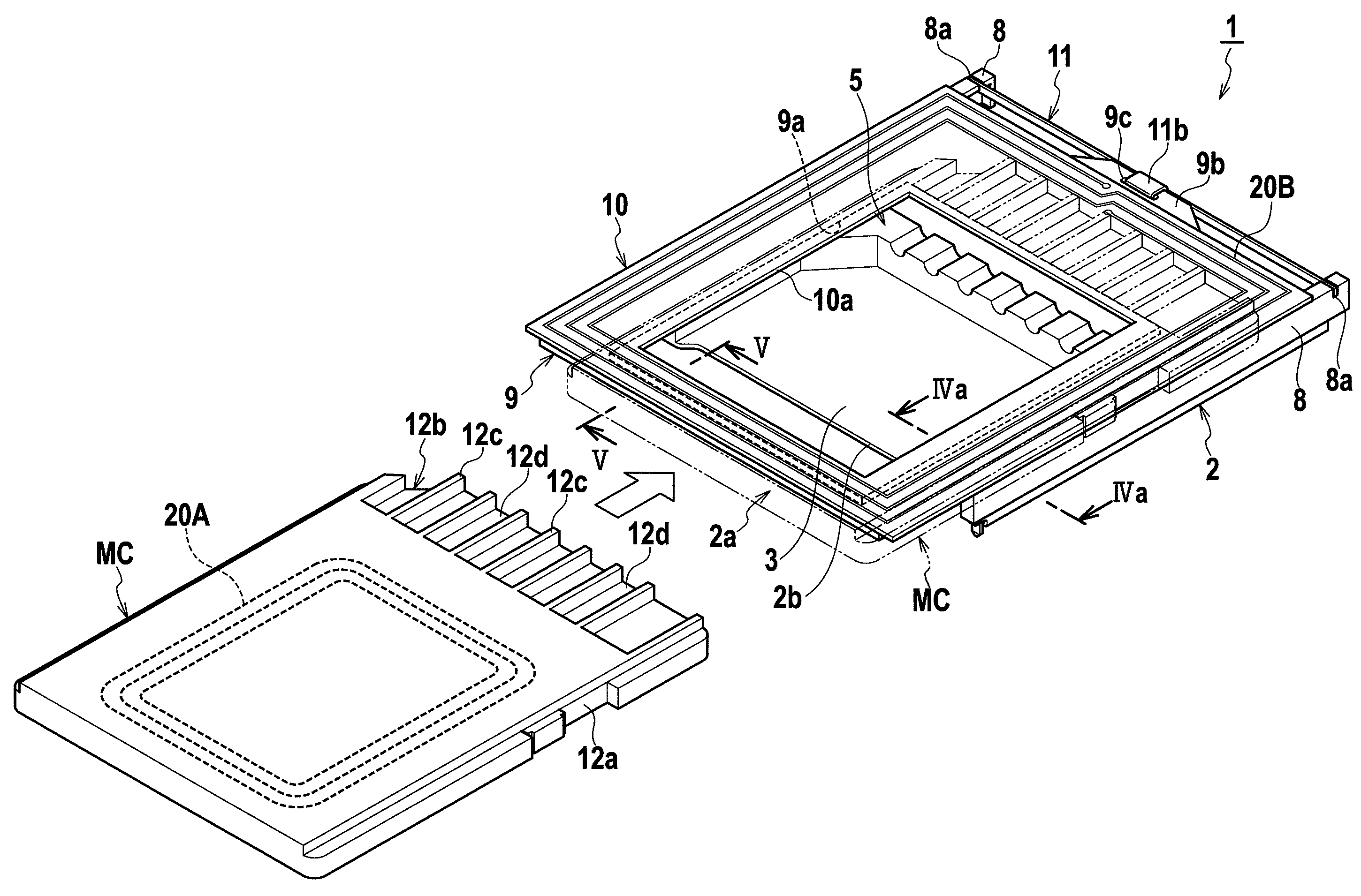
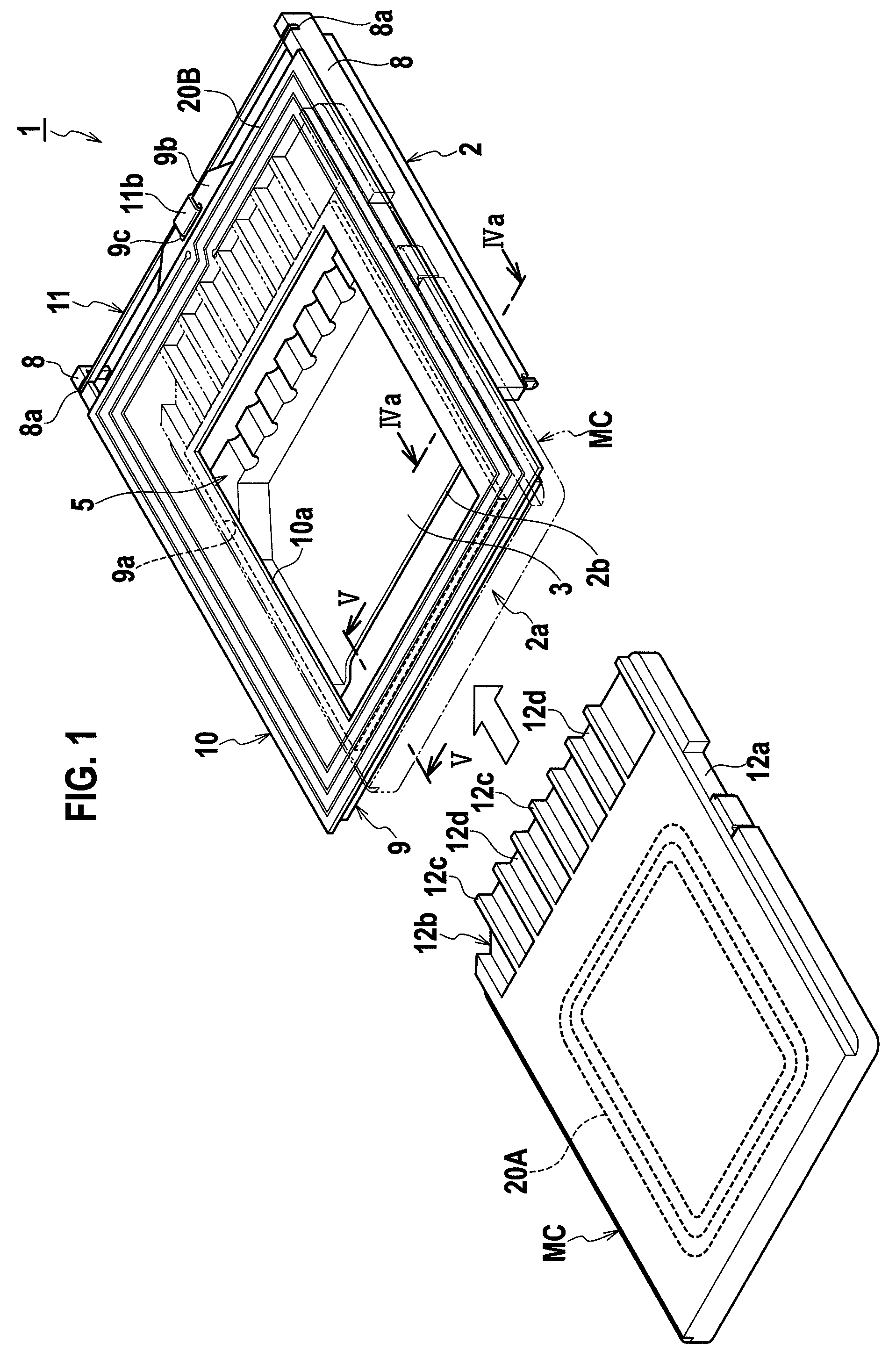
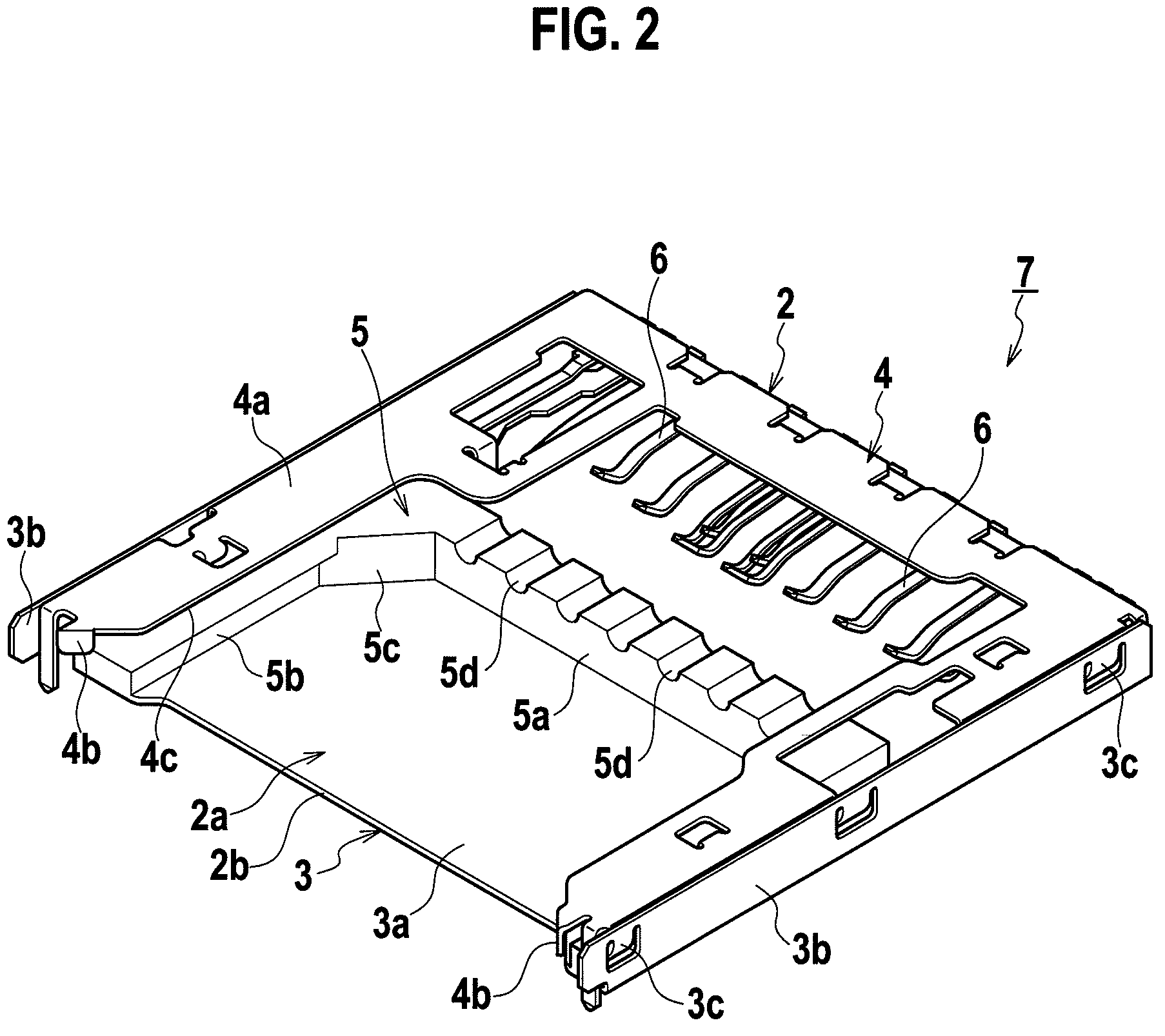
[0030]FIG. 1 is a perspective view of a memory card socket and a memory card according to a first embodiment of the present invention. FIG. 2 is a perspective view of a socket block included in the memory card socket according to the embodiment of the invention. FIG. 3 is an exploded perspective view of an antenna block included in the memory card socket according to the first embodiment of the invention. FIG. 4 show a guide member for movably guiding the antenna block included in the memory card socket according to the embodiment of the invention, where (a) is a sectional view taken along a line IVa-IVa in FIG. 1, and (b) is a sectional view taken along a line IVb-IVb in (a). FIG. 5 is a sectional view taken along a line V-V in FIG. 1. FIG. 6 show a leaf spring used in the memory card socket according to the embodiment of the invention, where (a) is a plan view and (b) is a side view. FIG. 7 show an operation of an antenna block in the memory card socket according to the first embo...

second embodiment

[0069]FIG. 8 is a perspective view of a memory card socket according to a second embodiment. FIG. 9 is a sectional view taken along a line IX-IX in FIG. 8. A memory card socket 1A according to the second embodiment has the same constituent elements as those of the memory card socket 1 according to the first embodiment. Like constituent elements are designated with like reference symbols, and redundant explanations will be omitted.

[0070]The memory card socket 1A according to the second embodiment is different from the memory card socket 1 according to the first embodiment in that a magnetic sheet 13 is provided inside of the coil of the secondary antenna 20B of an antenna block 17A instead of forming the cavity, and other structure is quite the same as that of the first embodiment.

[0071]That is, in this embodiment, a recess 9Ab (FIG. 9) is formed in a peripheral edge of a rectangular opening 9Aa of a base plate 9A, a peripheral edge of the rectangular magnetic sheet 13 is placed on t...

third embodiment

[0075]FIG. 10 is a perspective view of the memory card socket of a third embodiment. FIG. 11 is an exploded perspective view of the memory card socket according to this embodiment. FIG. 12 is a sectional view taken along a line XII-XII in FIG. 10. The memory card socket 1B according to the third embodiment has like constituent elements as those of the memory card socket 1 according to the first embodiment. Like constituent elements are designated with like reference symbols, and redundant explanations will be omitted.

[0076]The memory card socket 1B according to the embodiment is different from that of the first embodiment in that an antenna block 17B (FIG. 11) is fixed to a socket block 7B.

[0077]That is, as shown in FIG. 11, in the socket block 7B, a base bottom wall 4a of the base shell 4 is cut and lifted to form latching pawls 4d, the latching pawls 4d are inserted into latching holes 10Bb and 9Bd formed in an antenna substrate 10B and a base plate 9B of the antenna block 17B, an...


PUM


Abstract

A memory card socket has a plate-like antenna block having a coil-like secondary antenna which is opposed to an antenna incorporated in a memory card in a state where the memory card is attached to the card receiving portion. Openings as cavities are formed in portions of the antenna block inside of the coil of the secondary antenna. With this structure, it is possible to obtain a memory card socket having a compact and simple structure and having a non-contact communication function capable of preventing producing cost from increasing.

Description

TECHNICAL FIELD[0001]The present invention relates to a memory card socket for holding a card-like compact storage media (hereinafter, memory card) which has an IC card function for sending and receiving data to and from outside by means of non-contact communication such that the memory card can be inserted into and removed from the memory card socket.BACKGROUND ART[0002]Conventionally, as data storing means in an electronic equipment such as a digital camera and a cellular phone, a memory card (e.g., a SD memory card (trademark) and a multimedia card (trademark)) having a nonvolatile memory such as a flash memory in a card-like housing have become widespread.[0003]As a memory card socket into and from which the memory card is inserted and removed, there is a known memory card socket having a case formed with a card receiving portion for receiving a thin plate-like memory card, and a slider which is held in the card receiving portion such that the slider can move forward and backwar...

Claims


Application Information

Patent Timeline
IPC IPC(8): H01R13/648H01R24/00
CPCG06K7/0047G06K7/10178H01R2201/02G06K19/07739G06K19/077H01R12/71H01R13/62
Inventor TANAKA, HIROHISANAMBOKU, MASATOYAMANA, MASAHITO
Owner MATSUSHITA ELECTRIC WORKS LTD
Why Eureka
Try Eureka