
Eureka
For R&D, Eureka makes reading and utilizing patents & technical documents easy.
Eureka AIR
Designed for self-driven R&D workflows. Generate viable solutions, solve complex R&D challenges, empower your innovation with AI.

Eureka Materials
Designed for material experts only. Revolutionize your material R&D, from search, analyze, to developing new materials.

TechResearch
Generate reliable direction feasibility study reports for your R&D in just a few steps.

TechSeek
Discover and master advanced knowledge NOW. Basics, ideas, possibilities, all at once.

TechMind
As an expert in R&D Theories, TechMind can generates customized viable solutions instantly.

TechRisk
Analyze your overall solution with one click, know your potential R&D risks in advance.

TechMonitor
Get weekly tech updates, stay abreast of the latest tech innovations and key insights.
System and process for generating hydroelectric power
- Summary
- Abstract
- Description
- Claims
- Application Information
AI Technical Summary
Benefits of technology
Problems solved by technology
Method used
Image

Examples
first embodiment
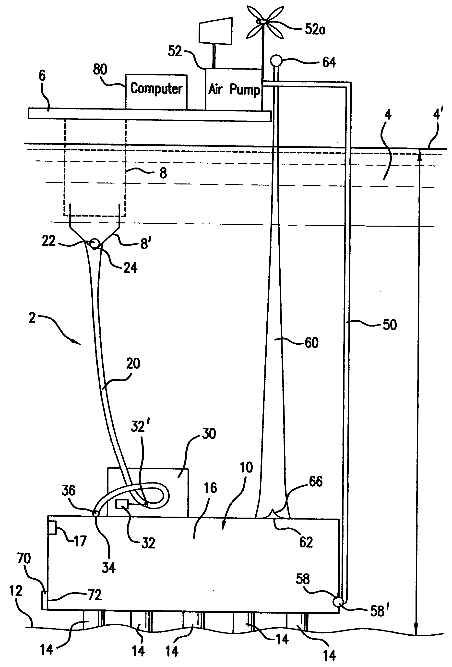
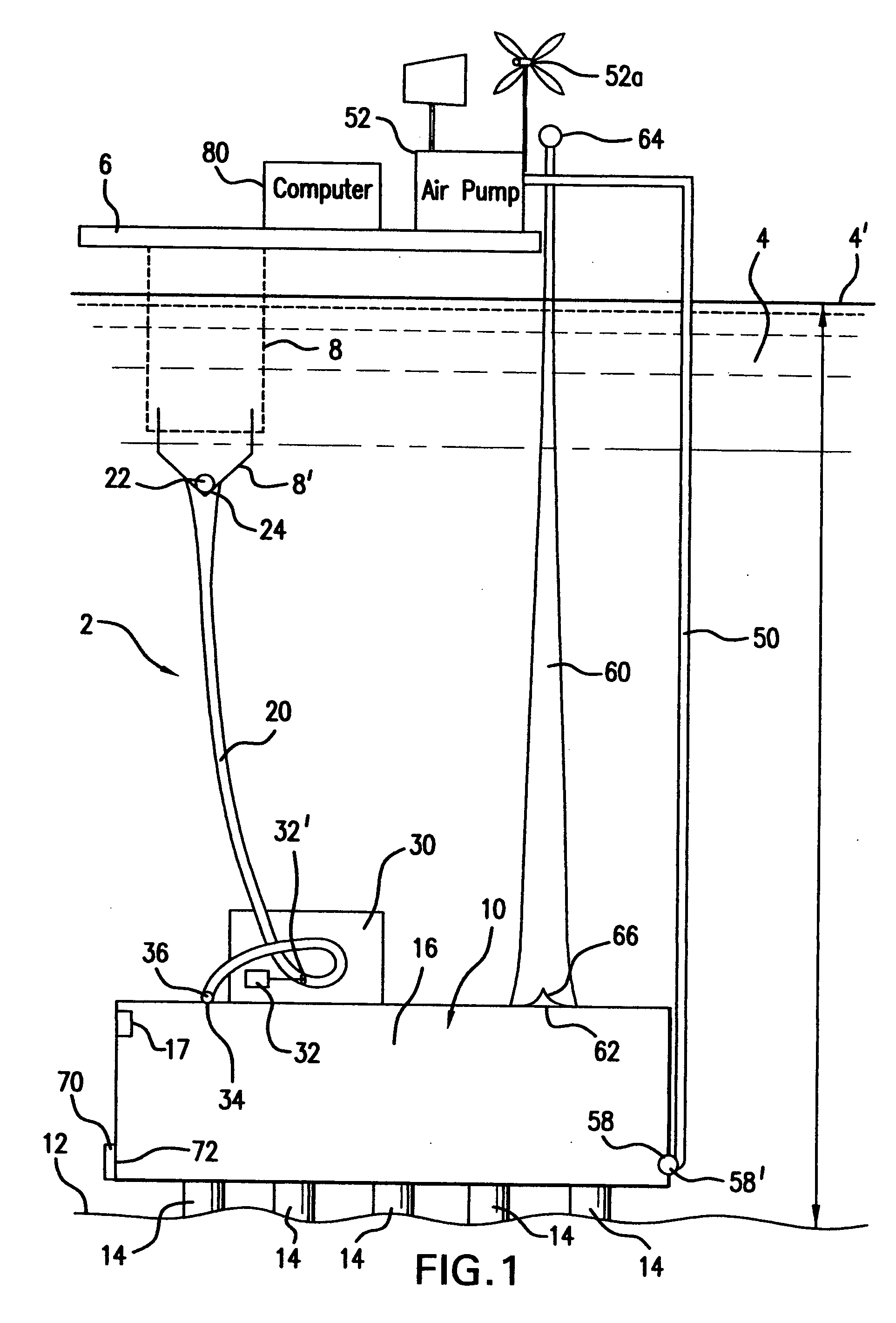
[0010]Referring to FIG. 1, there is illustrated the system for generating hydroelectric power in accordance with the invention, generally designated by reference numeral 2. The system 2 uses components submerged in a body of water 4, such as an ocean, lake, sea, bay and the like, that extract the energy derived from the pressure head present at a predetermined depth. An upper platform 6 is mounted above the water surface 4′ at a selected height. The platform 6 can comprise any known platform design that employs support columns (not shown) extending to the floor of the body 4 of water. Other methods of supporting the platform 6 may be employed, whether structural or using flotation means. The platform 6 carries a plurality of downward extending cable attachments 8, such as, for example, four or more in number. Other support devices such as struts and the like may be used in place of the cables 8. The cables 8 support an enlarged water intake 8′ at a position submerged beneath the sur...
second embodiment
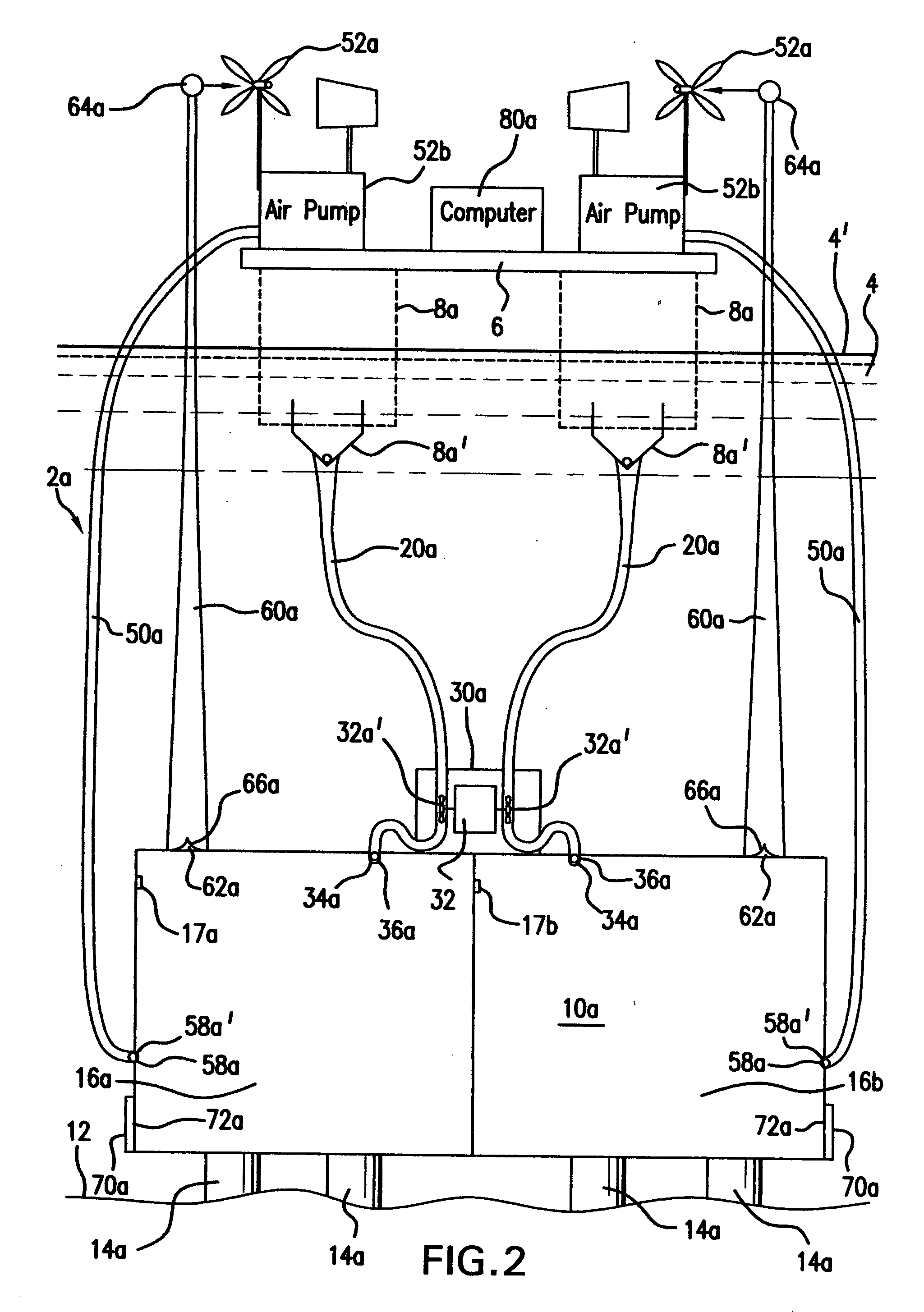
[0014]Referring now to FIG. 2, there is illustrated the invention, generally designated by reference numeral 2a. For a greater and more continuous power output, the system 2a establishes a plurality of water flows to generate electricity in two successive cycles, such as two separate flows as shown in FIG. 2. If desired, it is within the scope of the invention to run the redundant components of FIG. 2 generally simultaneously if desired. It should further be clear that system 2a could be modified further by employing more than two conduits establishing more than two water flows to generate electricity.
[0015]In FIG. 2, an upper platform 6a is elevated above the water surface 4′ at a selected height. Cables 8a support a pair of enlarged water intakes 8a′ beneath the surface 4′ of the body of water. A sealed reservoir 10a is mounted on the bottom 12 of the body of water by legs or pillars 14a. The reservoir 10a is sealed to selectively contain air within a pair of interior chambers 16a...
PUM
 Abstract
Description
Claims
Application Information
 - R&D Engineer
- R&D Manager
- IP Professional
- Industry Leading Data Capabilities
- Powerful AI technology
- Patent DNA Extraction
Browse by: Latest US Patents, China's latest patents, Technical Efficacy Thesaurus, Application Domain, Technology Topic, Popular Technical Reports.
© 2024 PatSnap. All rights reserved.Legal|Privacy policy|Modern Slavery Act Transparency Statement|Sitemap|About US| Contact US: help@patsnap.com