Non-contact charging apparatus having charging information display function and method thereof

a charging information and display function technology, applied in the direction of electrochemical generators, secondary cells servicing/maintenance, transportation and packaging, etc., can solve the problems of user not being able to perform various functions, large capacity batteries that meet user's needs have not been developed, and charging methods based on remaining battery life are not properly performed

Inactive Publication Date: 2009-06-11
LG ELECTRONICS INC
View PDF9 Cites 143 Cited by
  • Summary
  • Abstract
  • Description
  • Claims
  • Application Information

AI Technical Summary

Problems solved by technology

However, a large capacity battery that meets a user's needs has not been developed.
A user may not be able to perform various functionality when charging a battery according to a charging time and a charging method based on a remaining battery life is not properly performed.
However, when the charging unit and the battery are respectively provided with the contact terminal, appearance may be degraded, and the charging unit and the battery may be exposed to various elements, such as humidity.
In this example, charging energy may be lost or charging may not be performed properly due to inferior contact between the charging unit and the battery.
However, the conventional non-contact charging method (inductive or capacitive coupling) has the following problems.
First, a user cannot easily determine an optimal position on the charging unit for charging efficiency.
Second, a user cannot accurately check a current charging status of the mobile terminal.

Method used


Image

  • Non-contact charging apparatus having charging information display function and method thereof
  • Non-contact charging apparatus having charging information display function and method thereof
  • Non-contact charging apparatus having charging information display function and method thereof

Examples


first embodiment

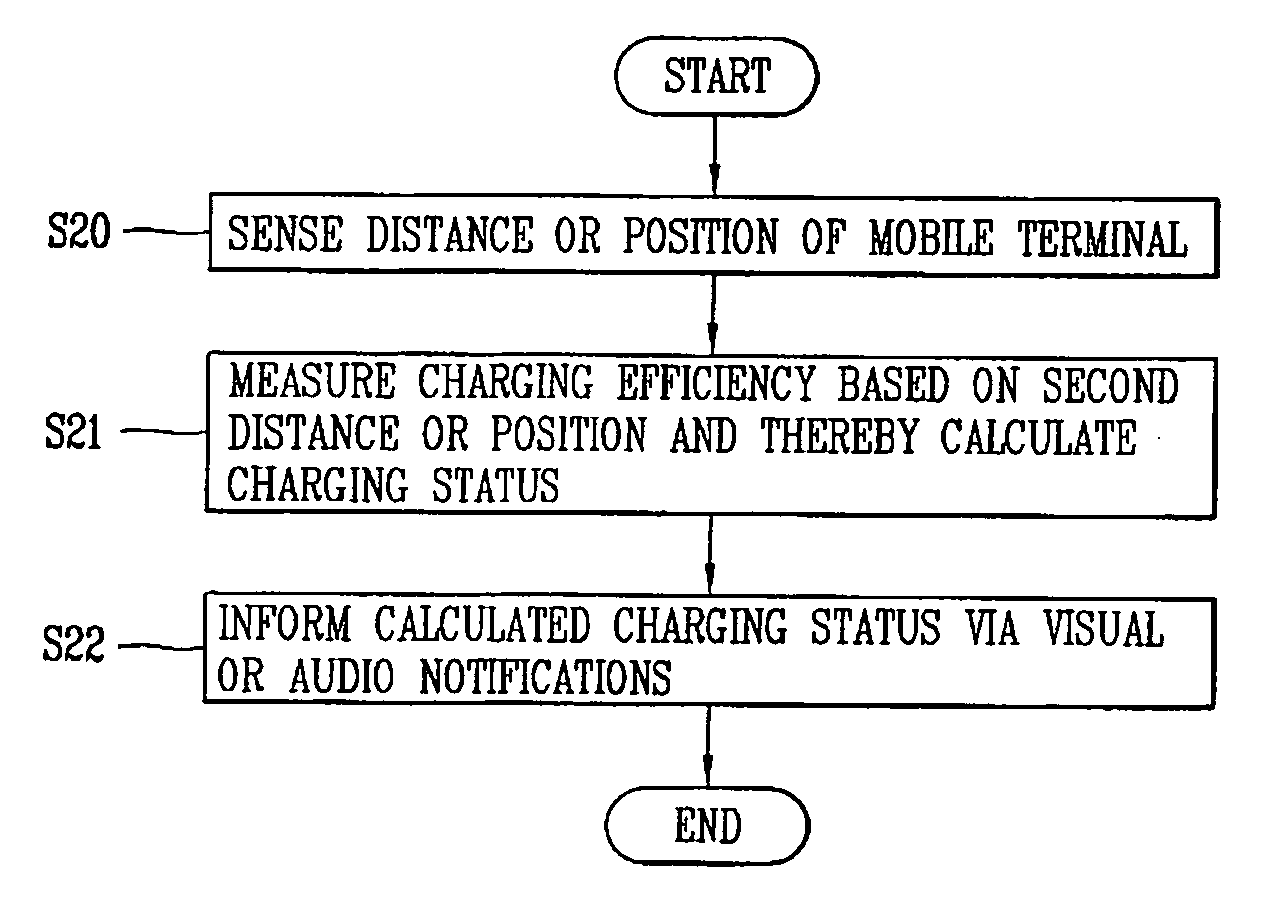
[0109]FIG. 5 illustrates a block diagram of a non-contact charging apparatus having a charging information display function according to the present invention.

[0110]As shown in FIG. 5, the non-contact charging apparatus having a charging information display function includes a charge object 400, which is an object to be charged in a non-contact manner, and a charging unit 410 configured to provide a current or a voltage for charging the charge object 400 in a non-contact manner. The charging unit 410 may be configured to display a charging efficiency according to a position of the charge object 400 relative to the charging unit 410. The charging unit may further output a charging status via visual or audio notifications.

[0111]The charge object 400 may include the mobile terminal 100 or a battery, such as power supply 190. The battery may be detachably mounted to the mobile terminal.

[0112]The charging unit 410 may include a controller 410-1 for measuring charging efficiency and charg...

second embodiment

[0127]FIG. 10 illustrates a block diagram of a non-contact charging apparatus in a capacitive coupling manner according to the present invention. For explanatory convenience, the charge object 400 is referenced as the mobile terminal 100.

[0128]As illustrated in FIG. 10, in the example of a non-contact charging method in a capacitive coupling manner, the mobile terminal 100 may include a load side flat type conductor 102 and the charging unit 410 may include a power side flat type conductor 402. The mobile terminal 100 is charged as the load side flat type of conductor 102 and the power side flat type of conductor 402 are capacitively coupled to each other.

[0129]In the example of a non-contact charging apparatus in a capacitive coupling manner, a charging efficiency of the mobile terminal 100 depends on the position of the mobile terminal 100 in relation to the power side flat type conductor 402 on the charging unit 410. Specifically, as illustrated in position D of FIG. 10, the mobi...


PUM

PropertyMeasurementUnit
areaaaaaaaaaaa
charge areaaaaaaaaaaa
strengthaaaaaaaaaa

Abstract

A non-contact charging apparatus having a charging information display function is presented. The non-contact charging apparatus includes a charging unit for charging a charge object in a non-contact manner placed in proximity to the charging unit, wherein the charging unit is configured to measure a charging efficiency and a charging status of the charge object on each position of the charging area, and to output the charging efficiency and the charging status via an output unit.

Description

CROSS-REFERENCE TO RELATED APPLICATIONS[0001]Pursuant to 35 U.S.C. § 119(a), this application claims the benefit of earlier filing date and right of priority to Korean Application No. 10-2007-0126389, filed on Dec. 6, 2007, the contents of which are hereby incorporated by reference herein in their its entiretyBACKGROUND OF THE INVENTION[0002]1. Field of the Invention[0003]The present invention relates to a non-contact charging apparatus having a charging information display function, and a method thereof.[0004]2. Discussion of the Related Art[0005]A mobile terminal is a device which may perform various functions. Examples of such functions include data and voice communications, capturing images and video via a camera, recording audio, playing music via a speaker system, and displaying images and video on a display. Some terminals include additional functionality which supports game playing, while other terminals are configured as multimedia players. More recently, mobile terminals h...

Claims


Application Information

Patent Timeline
Patent Type & Authority Applications(United States)
IPC IPC(8): H02J7/00H01M10/44H01M10/46H01M10/48H02J7/02H02J50/00H02J50/05H02J50/10
CPCH02J7/025Y02B40/90H04M2250/12H04M1/72519H02J7/0042Y02B40/00H02J50/80H02J50/90H02J50/10H04M1/724H04B1/40H02J50/05
Inventor LEE, DONG-JO
Owner LG ELECTRONICS INC
Why Eureka
Try Eureka