Liquid supply device and liquid ejecting apparatus

Active Publication Date: 2009-06-11
SEIKO EPSON CORP
View PDF5 Cites 16 Cited by
  • Summary
  • Abstract
  • Description
  • Claims
  • Application Information

AI Technical Summary

Benefits of technology

[0010]With this configuration, if the pump performs a pump action, the liquid is sucked into the pump chamber from the upstream side as the liquid supply source side through the first one-way valve, and the liquid is ejected from the pump chamber toward the downstream side and passes through the second one-way valve. The liquid passing through the second one-way valve is temporarily stored in the pressure accumulation chamber of the liquid pressure accumulation unit. In this case, the pressure accumulation chamber of the liquid pressure accumulation unit has a variable volume. Accordingly, when an urging force is applied in a direction to decrease the volume, the liquid in the pressure accumulation chamber is stored in a pressure-accumulated state. A backflow of the liquid stored in the pressure-accumulated state toward the pump chamber is suppressed by the second one-way valve, and the liquid is pressurized and supplied toward the downstream side, on which the liquid is consumed. For this reason, the liquid can be stably pressurized and supplied from the upstream side as the liquid supply source side toward the downstream side, on which the liquid is consumed, without adversely affecting the state of the pump, which repeatedly performs liquid suction and ejection actions.
[0030]With this configuration, the liquid supplied from the liquid supply device is temporarily stored in the valve unit, and the liquid is supplied to the liquid ejecting head in an amount corresponding to the amount of the liquid consumed by the liquid ejecting head. For this reason, the pressurized liquid can be prevented from being directly supplied to the liquid ejecting head, and thus liquid leakage from the liquid ejecting head can be suppressed.

Problems solved by technology

As a result, in the printer in which the pump is provided in the ink flow channel connecting the ink cartridge and the recording head, during the pump action, ink for printing may not be ejected from the recording head for a moment.

Method used


Image

  • Liquid supply device and liquid ejecting apparatus
  • Liquid supply device and liquid ejecting apparatus
  • Liquid supply device and liquid ejecting apparatus

Examples


Embodiment Construction

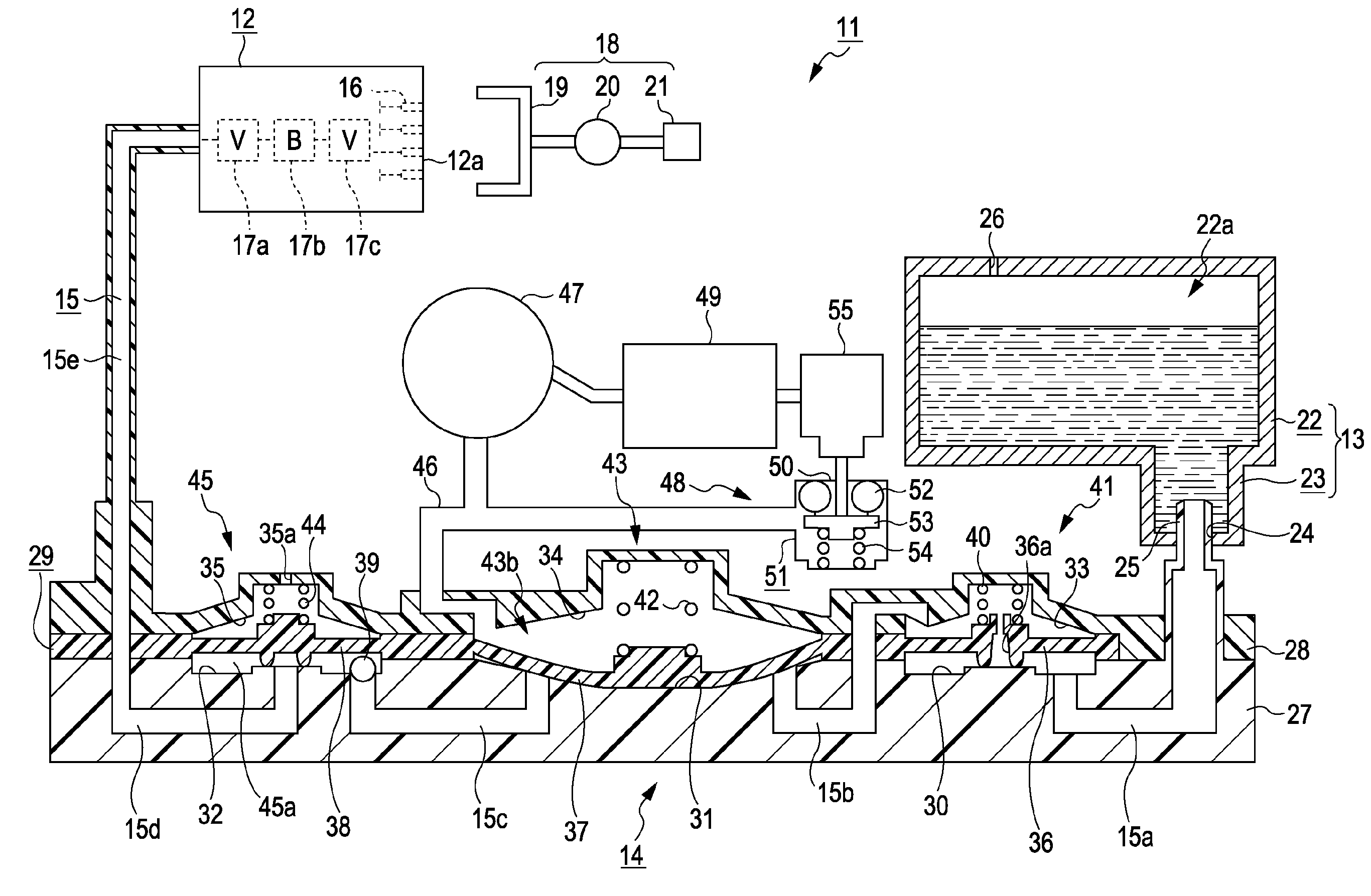
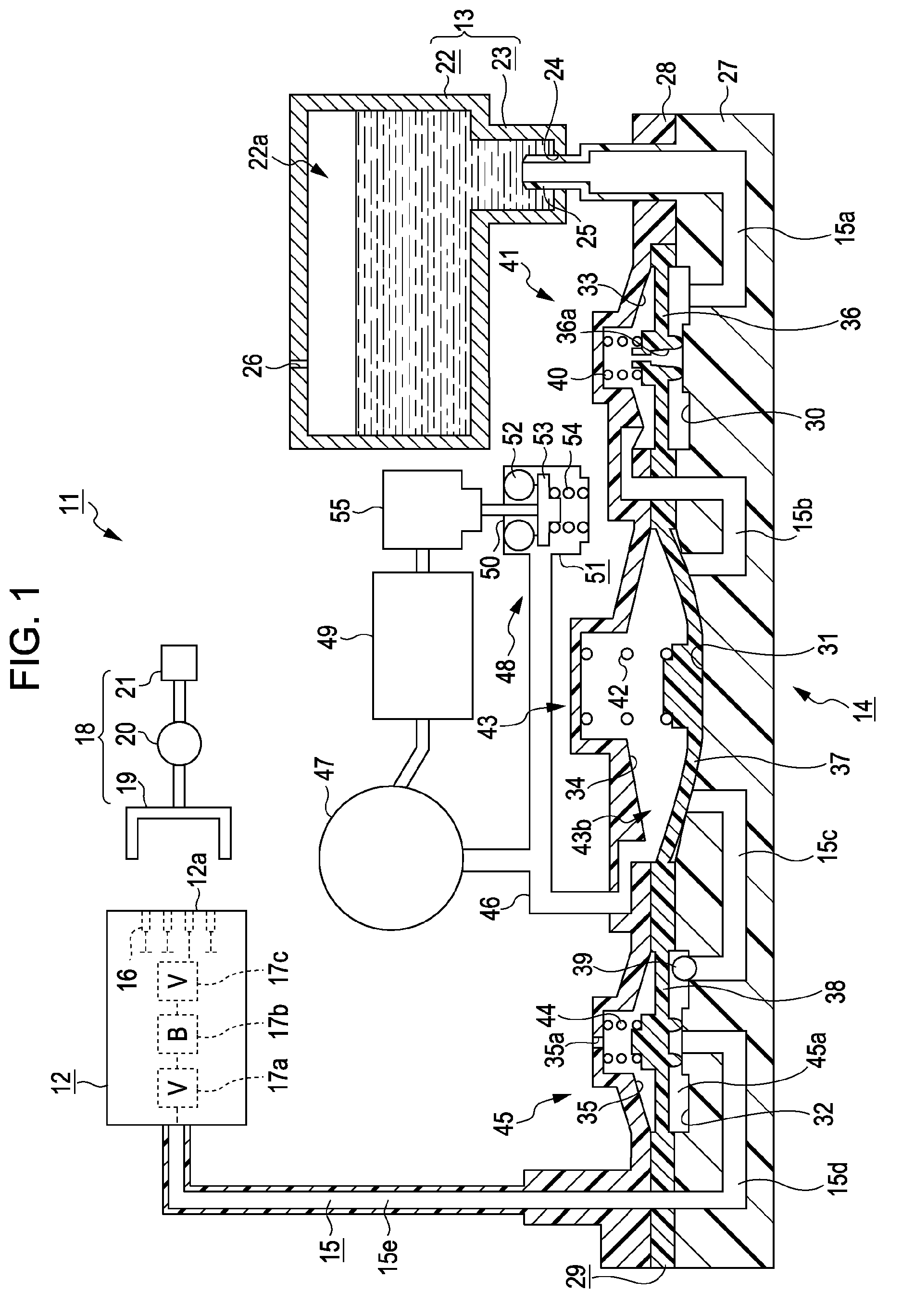
[0037]Hereinafter, an embodiment in which the invention is applied to an ink jet recording apparatus (hereinafter, referred to as “printer”), which is a kind of liquid ejecting apparatus, will be described with reference to FIGS. 1 to 3B.

[0038]As shown in FIG. 1, a printer 11 of this embodiment includes a recording head 12 serving as a liquid ejecting head that ejects ink (liquid) onto a target (not shown), and an ink supply device 14 serving as a liquid supply device that supplies, to the recording head 12, ink contained in an ink cartridge 13 serving as a liquid supply source. An ink flow channel (liquid supply channel) 15 is provided through which ink is supplied from an upstream side toward a downstream side, that is, from the ink cartridge 13 toward the recording head 12, in a state where an upstream end of the ink supply device 14 is connected to the ink cartridge 13, and a downstream end of the ink supply device 14 is connected to the recording head 12.

[0039]The printer 11 in...


PUM


Abstract

A liquid supply device includes a liquid supply channel that supplies a liquid from an upstream side as a liquid supply source side to a downstream side, where the liquid is consumed, and a pump that pumps a part of the liquid supply channel as a pump chamber. A first one-way valve in the liquid supply channel on an upstream side from the pump chamber permits ink to flow from the upstream side to the downstream side. A second one-way valve on a downstream side from the pump chamber permits ink to flow from the upstream side toward the downstream side. A liquid pressure accumulation unit with a volume variable pressure accumulation chamber is disposed on a downstream side from the second one-way valve to form a part of the liquid supply channel and stores the liquid in a pressure-accumulated state within the pressure accumulation chamber.

Description

BACKGROUND[0001]The entire disclosure of Japanese Patent Application No. 2007-319815, filed Dec. 11, 2007 and Japanese Patent Application No. 2008-222047, filed Aug. 29, 2008, are expressly incorporated herein by reference.[0002]1. Technical Field[0003]The present invention relates to a liquid supply device that supplies a liquid from an upstream side as a liquid supply source side to a downstream side, on which the liquid is consumed, and a liquid ejecting apparatus.[0004]2. Related Art[0005]An ink jet printer (hereinafter, simply referred to as “printer”) is a known example of a liquid ejecting apparatus for ejecting a liquid onto a target. This printer ejects ink (liquid), which is supplied to a recording head (liquid ejecting head), from nozzles formed in the recording head, thereby performing printing on a recording medium as the target. In recent years, as described in JP-A-2006-272661, a printer is suggested in which a pump is provided in an ink flow channel connecting an ink...

Claims


Application Information

Patent Timeline
IPC IPC(8): B41J2/04
CPCB41J2/17596
Inventor YOKOUCHI, HIDEYA
Owner SEIKO EPSON CORP
Why Eureka
Try Eureka