Pressure regulating unit, liquid supplying apparatus, and liquid ejecting apparatus

a technology of pressure regulating unit and liquid ejecting device, which is applied in the direction of printing, etc., can solve the problems of liquid leakage from the ejector port, and achieve the effect of suppressing liquid leakage and stabilizing the pressure of the second pressure chamber

Active Publication Date: 2015-11-05
CANON KK
View PDF3 Cites 0 Cited by
  • Summary
  • Abstract
  • Description
  • Claims
  • Application Information

AI Technical Summary

Benefits of technology

[0012]According to the present invention, it is possible to stably maintain the pressure of the second pressure chamber by applying the urging force to the valve for adjusting the opening degree of the communication path between the first pressure chamber and the second pressure chamber, the urging force acting in the direction in which the communication path is closed and changing according to the pressure of the first pressure chamber. In a case of supplying the liquid from the second pressure chamber to the liquid ejection head, it is possible to maintain the negative pressure of the liquid contained in the liquid ejection head in a predetermined range to suppress the leakage of the liquid from the liquid ejection head.

Problems solved by technology

Therefore, the negative pressure to be applied to the ink staying in the print head becomes low during the stoppage of the printing apparatus and during the exchange of the print head, thus causing a possibility of leakage of the ink from the ejection port.

Method used


Image

  • Pressure regulating unit, liquid supplying apparatus, and liquid ejecting   apparatus
  • Pressure regulating unit, liquid supplying apparatus, and liquid ejecting   apparatus
  • Pressure regulating unit, liquid supplying apparatus, and liquid ejecting   apparatus

Examples


example 1

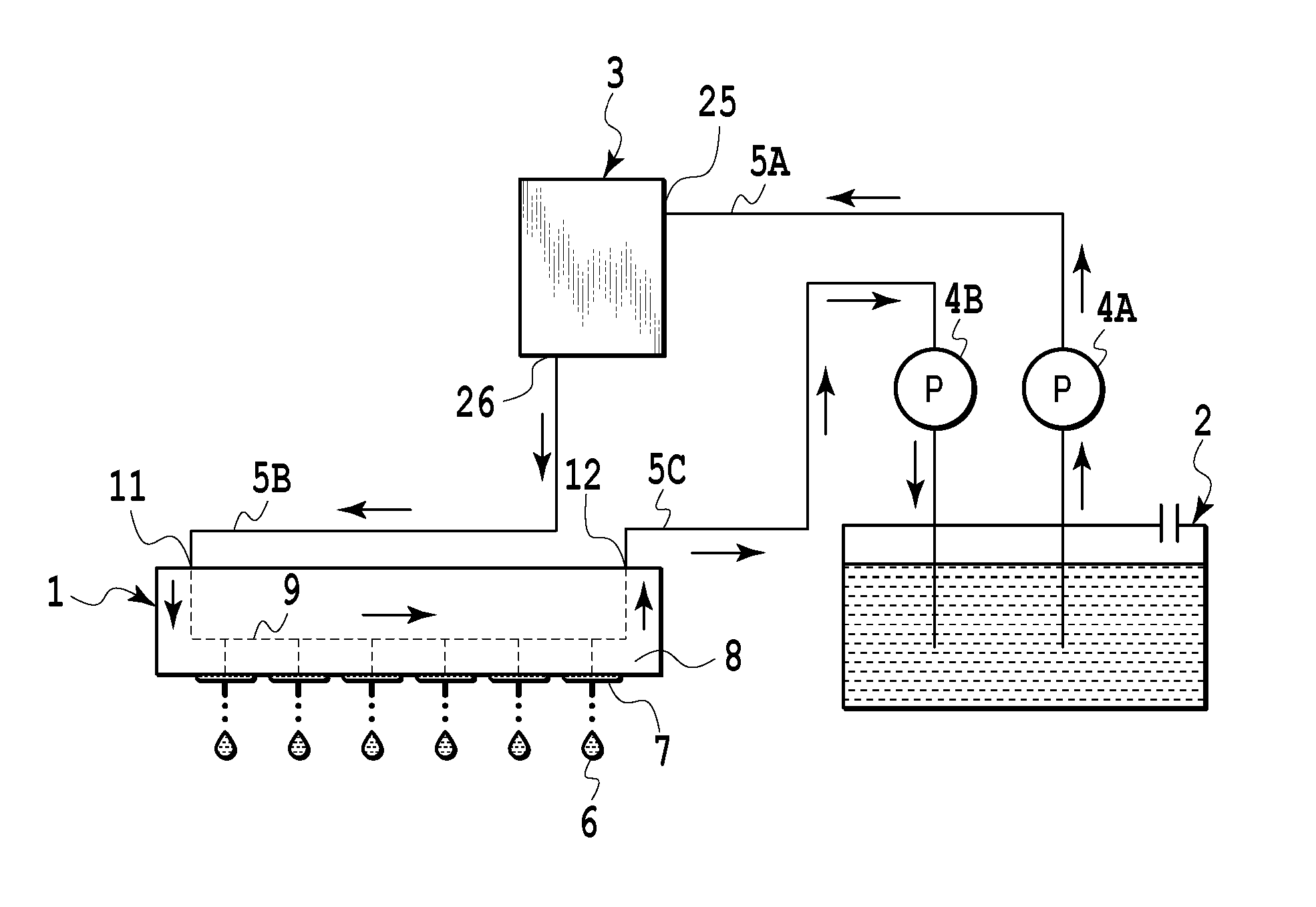
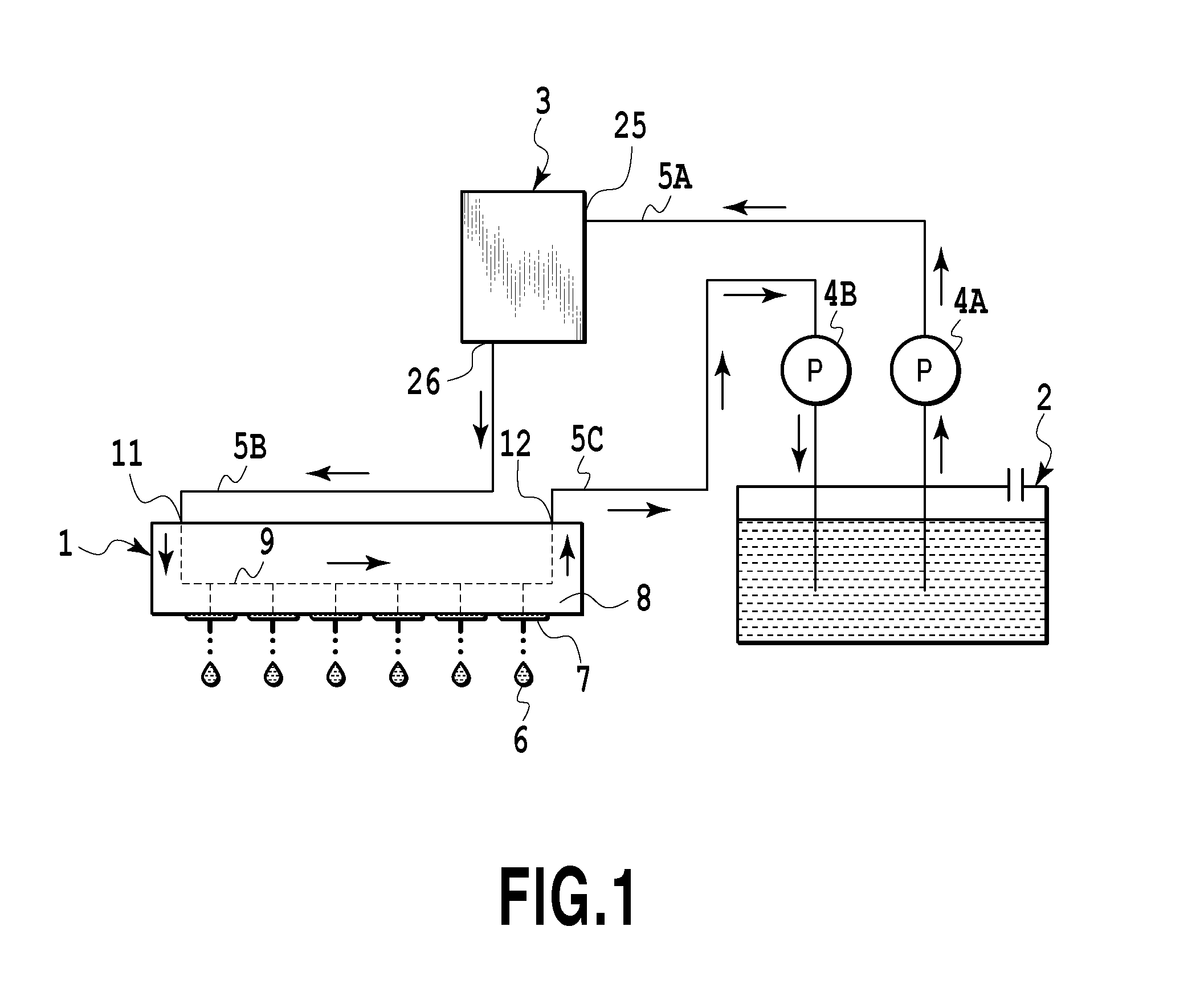
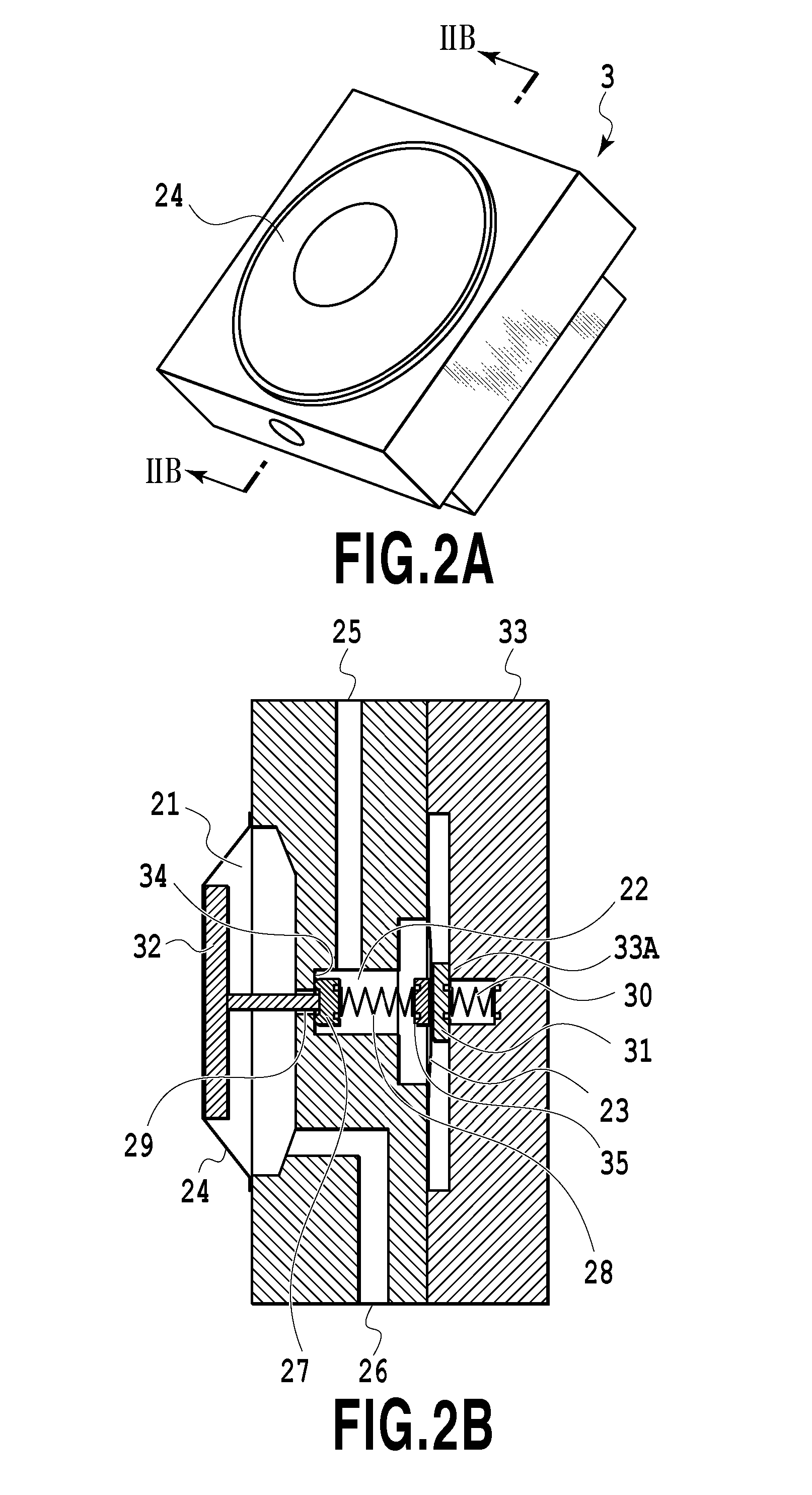
[0045]In Example 1, the pressure regulating unit 3 shown in FIG. 2A is fabricated under the condition shown in Table (1) below, thus configuring the ink supplying apparatus shown in FIG. 1. In the ink supplying apparatus, a pressure of ink staying in the pressure chamber 21 in a case where the pressurizing pump 4A is driven to pressurize ink at 50 kPa (a pressure during pressurization) and a pressure of ink staying in the pressure chamber 21 in a case of stopping the pressurizing pump 4A (a pressure during the stoppage of pressurization) are shown in Table (2) below.

TABLE (1)ComparativeExample 1ExampleArea of valve (mm2)4.54.5Area of negative pressure plate (mm2)530530Spring constant of valve spring (gf / mm)4.24.2Initial urging force of valve spring (gf)5151Urging force of urging member (gf)500

TABLE (2)Compar-Exam-Exam-ativeple 1ple 2ExampleDuring pressurization: 50 kPa (mmAq)−97−97−97During stoppage of−94−92−51pressurization: 0 kPa (mmAq)

[0046]In Comparative Example, a pressure regu...

example 2

[0049]In Example 2, a pressure regulating unit 3 as shown in FIG. 7 is fabricated under the condition shown in Table (3) below. The pressure regulating unit 3 is configured to use a tension of the film 23 instead of the urging force of the first urging member 30. That is to say, the film 23 is configured to function as the first urging member 30. The ink supplying apparatus shown in FIG. 1 is configured by using such a pressure regulating unit. In the ink supplying apparatus, a pressure of ink staying in the pressure chamber 21 in a case where the pressurizing pump 4A is driven to pressurize ink at 50 kPa (a pressure during pressurization) and a pressure of ink staying in the pressure chamber 21 in a case of stopping the pressurizing pump 4A (a pressure during the stoppage of pressurization) are shown in Table (2).

TABLE (3)Example 2Area of valve (mm )4.5Area of negative pressure plate (mm2)530Spring constant of valve spring (gf / mm)4.2Initial urging force of valve spring (gf)51Tensio...


PUM


Abstract

The present invention provides a pressure regulating unit capable of applying a stable pressure so as to supply liquid, a liquid supplying apparatus, and a liquid ejecting apparatus. An ink communication path allows an ink introducing chamber communicating with an ink inlet and a pressure chamber communicating with an ink outlet to communicate with each other. A valve including a valve body and a valve seat adjusts the opening degree of the ink communication path. An urging member applies, to the valve, an urging force that acts in a direction in which the ink communication path is closed and increases according to an increase in pressure in the ink introducing chamber.

Description

BACKGROUND OF THE INVENTION[0001]1. Field of the Invention[0002]The present invention relates to a pressure regulating unit for regulating pressure to be applied to liquid, a liquid supplying apparatus provided with the pressure regulating unit, and a liquid ejecting apparatus.[0003]2. Description of the Related Art[0004]A liquid ejecting apparatus is exemplified by an inkjet printing apparatus for ejecting ink (liquid) supplied from an ink tank (liquid container) through an inkjet print head (liquid ejection head) so as to print an image on a print medium. In, for example, a business-grade printing apparatus requiring an improved print speed as the printing apparatus, a large quantity of ink is ejected from the print head. In view of this, a large quantity of ink is required to be supplied to the print head. For this purpose, ink contained in the ink tank is pressurized by a pump or the like, and then, the pressurized ink need be supplied (pressure-supplied). In the meantime, ink, ...

Claims


Application Information

Patent Timeline
Patent Type & Authority Applications(United States)
IPC IPC(8): B41J2/175
CPCB41J2/17596B41J2/175B41J2/18
Inventor MORIGUCHI, TAKUTOIWANAGA, SHUZOYAMADA, KAZUHIROTAMENAGA, ZENTAROMORIYA, TAKATSUGU
Owner CANON KK
Why Eureka
Try Eureka