
Lighting handle of car

Inactive Publication Date: 2009-06-11
WANG MING CHENG
View PDF4 Cites 27 Cited by
  • Summary
  • Abstract
  • Description
  • Claims
  • Application Information

AI Technical Summary

Benefits of technology

[0003]According, the main object of the present invention is to provide a device which increases the alert effect at the lateral sides of the car. This function is especially used as the car changes direction.

Problems solved by technology

The lights of cars are installed at the front or rear sides of the cars and thus the alert effect is limited at the front and rear sides.
Therefore, for the people or cars at the lateral sides, no alert is provided and they can not keep attention to the movement of the cars.
Thus, they feel danger in driving.

Method used


Image

  • Lighting handle of car
  • Lighting handle of car
  • Lighting handle of car

Examples


Embodiment Construction

[0011]In order that those skilled in the art can further understand the present invention, a description will be provided in the following in details. However, these descriptions and the appended drawings are only used to cause those skilled in the art to understand the objects, features, and characteristics of the present invention, but not to be used to confine the scope and spirit of the present invention defined in the appended claims.

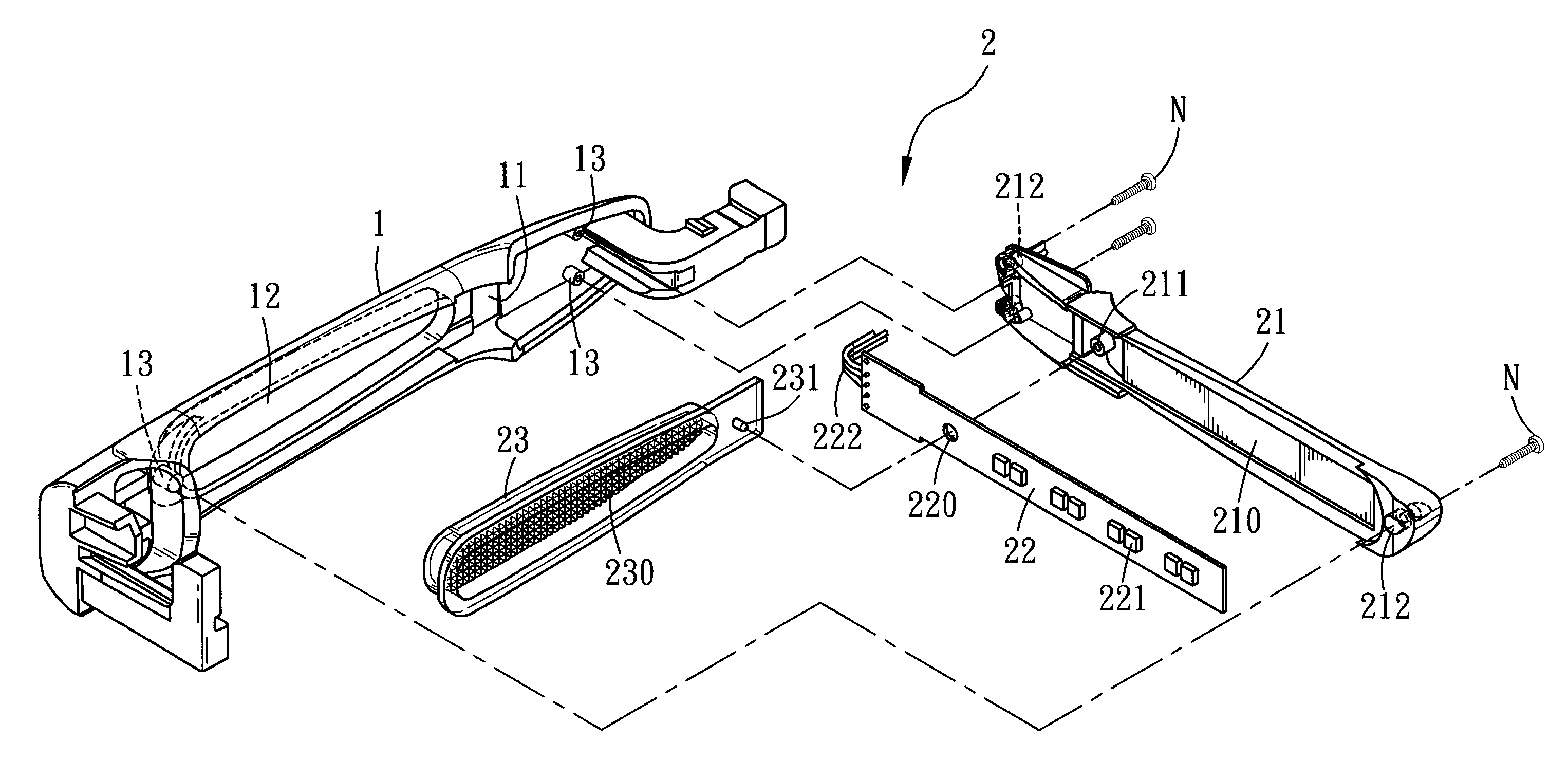
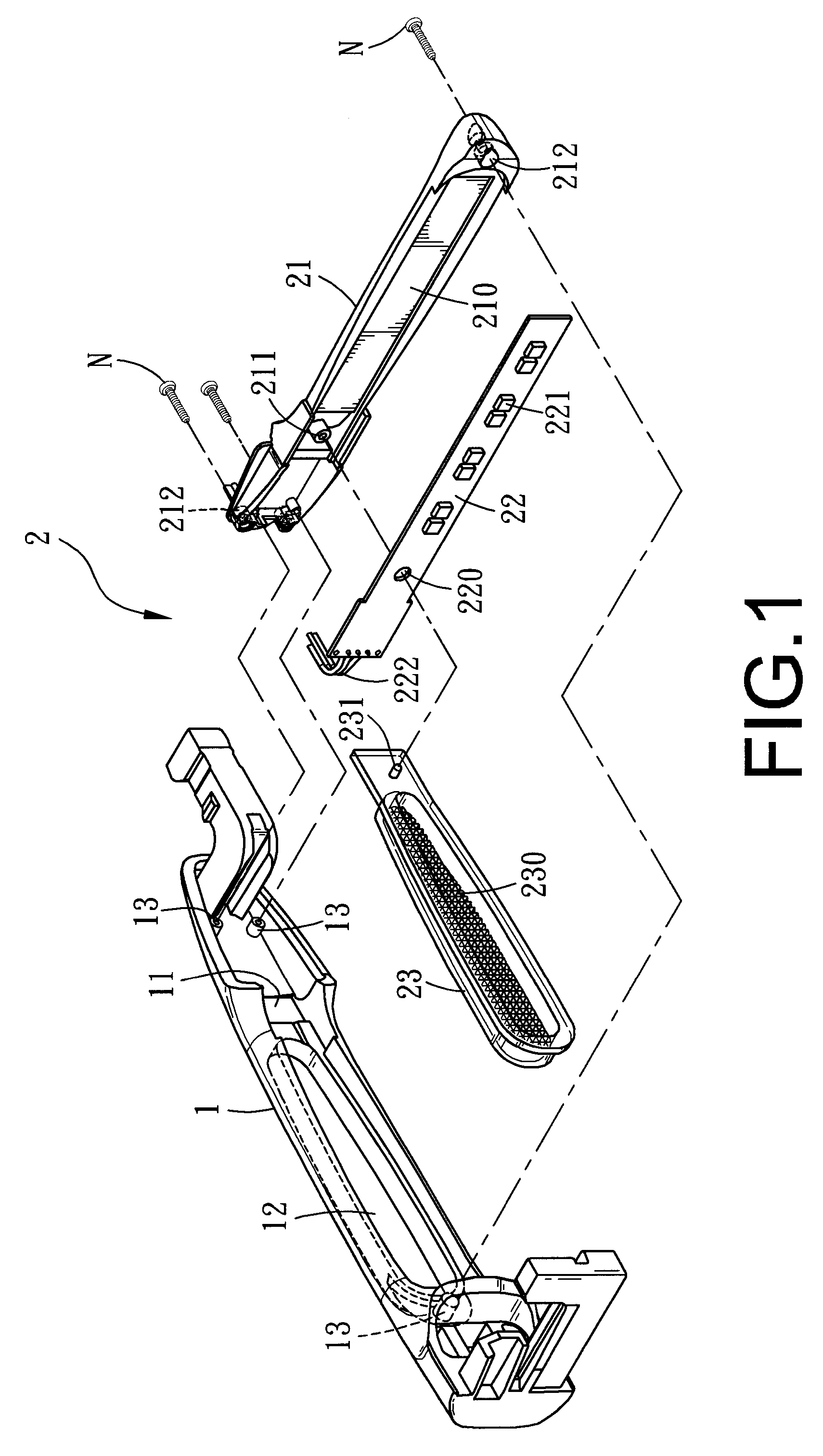
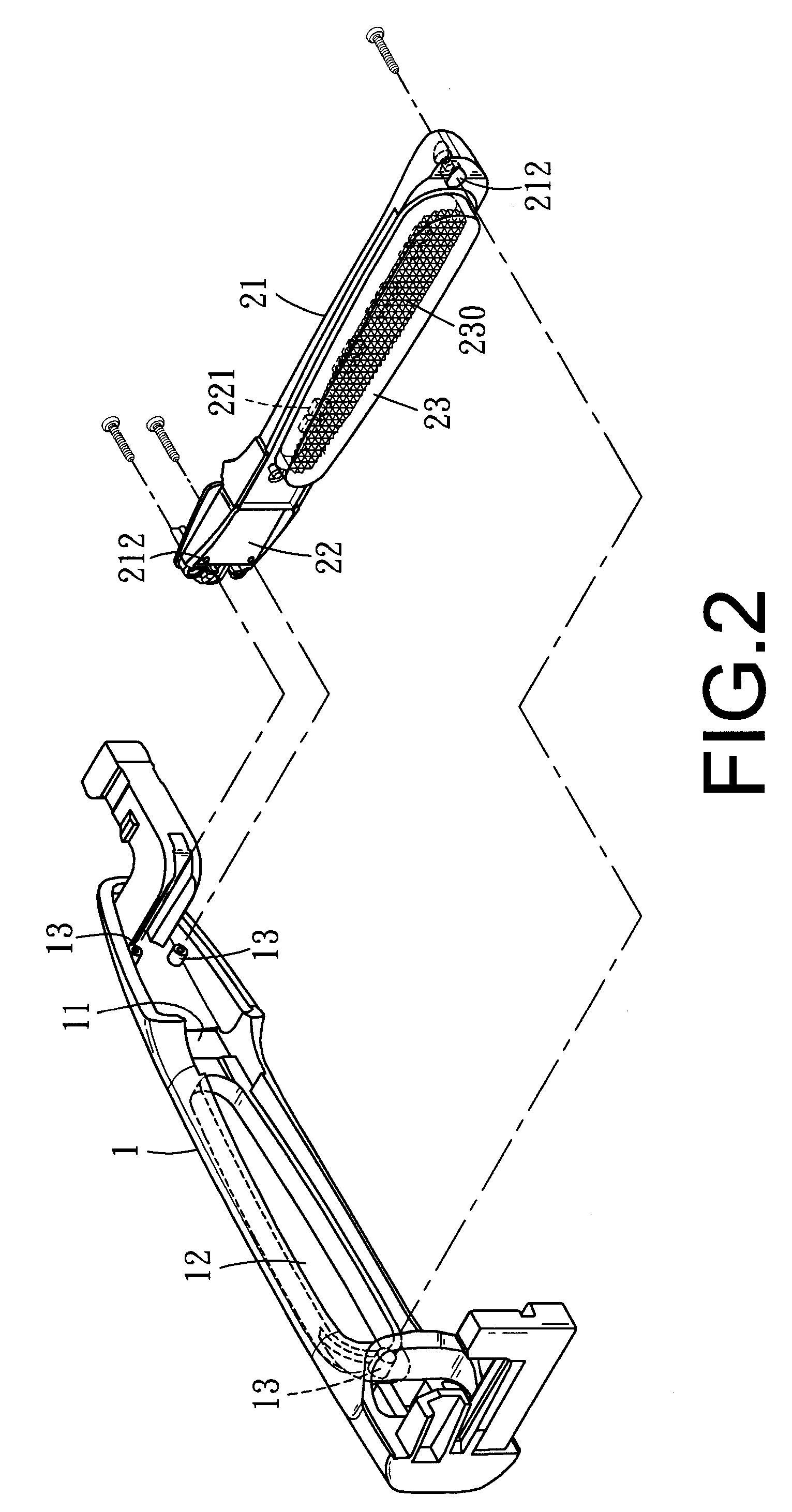
[0012]Referring to FIG. 1, the present invention mainly has the following elements.

[0013]A handle body 1 has a recess 11 at an inner surface thereof. The recess 11 has a long via hole 12 at a middle section thereof. Each of two ends of the recess 11 has a post 13.

[0014]A light emitting device 2 is installed at an inner side of the recess 11 of the handle body 1. The light emitting device 2 includes the following elements. A seat 21 is installed with a supporting surface 210. One side of the supporting surface 210 is formed with an inserting groove ...


PUM


Abstract

A lighting handle of a car comprises a handle body having a recess at an inner surface thereof; a light emitting device being installed at an inner side of the recess of the handle body; the light emitting device including: a seat installed with a supporting surface; one side of the supporting surface being formed with an inserting groove; a circuit board installed on the supporting surface of the seat; the circuit board being installed with a plurality of lighting emitting bodies; the circuit board having a power wire for connecting other electric circuit in a car; and a transparent lamp cover installed on the seat; an inner wall of the cover being a reflecting surface; one side of the cover having a protrusion which has passed through the through hole of the circuit board to be inserted into the inserting groove of the seat.

Description

FIELD OF THE INVENTION[0001]The present invention relates to handles, in particular to a lighting handle of a car, which has lights at the handle so that the lateral sides of the car can provide the alert effect. Thus, peoples or drivers near the lateral sides of the car can have the alert about the states of the car from the lighting handle of the car.BACKGROUND OF THE INVENTION[0002]Generally, the handles of car doors are used for opening or closing the doors. The lights of cars are installed at the front or rear sides of the cars and thus the alert effect is limited at the front and rear sides. No alert is provided at the lateral sides of the cars. Therefore, for the people or cars at the lateral sides, no alert is provided and they can not keep attention to the movement of the cars. Thus, they feel danger in driving. As a result, there is an eager demand for resolving this problem.SUMMARY OF THE INVENTION[0003]According, the main object of the present invention is to provide a d...

Claims


Application Information

Patent Timeline
IPC IPC(8): B60Q1/00
CPCB60Q1/2669
Inventor WANG, MING-CHENG
Owner WANG MING CHENG
Learn More