
Parallel connected inverters

a technology of parallel connection and inverter, which is applied in direction finders, dc-ac conversion without reversal, instruments, etc., can solve the problems of large conduction loss and arrangement not operating at best achievable efficiency

Active Publication Date: 2009-06-11
SOLAREDGE TECH LTD
View PDF99 Cites 248 Cited by
  • Summary
  • Abstract
  • Description
  • Claims
  • Application Information

AI Technical Summary

Benefits of technology

[0009]The following summary of the invention is included in order to provide a basic understanding of some aspects and features of the invention. This summary is not an extensive overview of the invention and as such it is not intended to particul...

Problems solved by technology

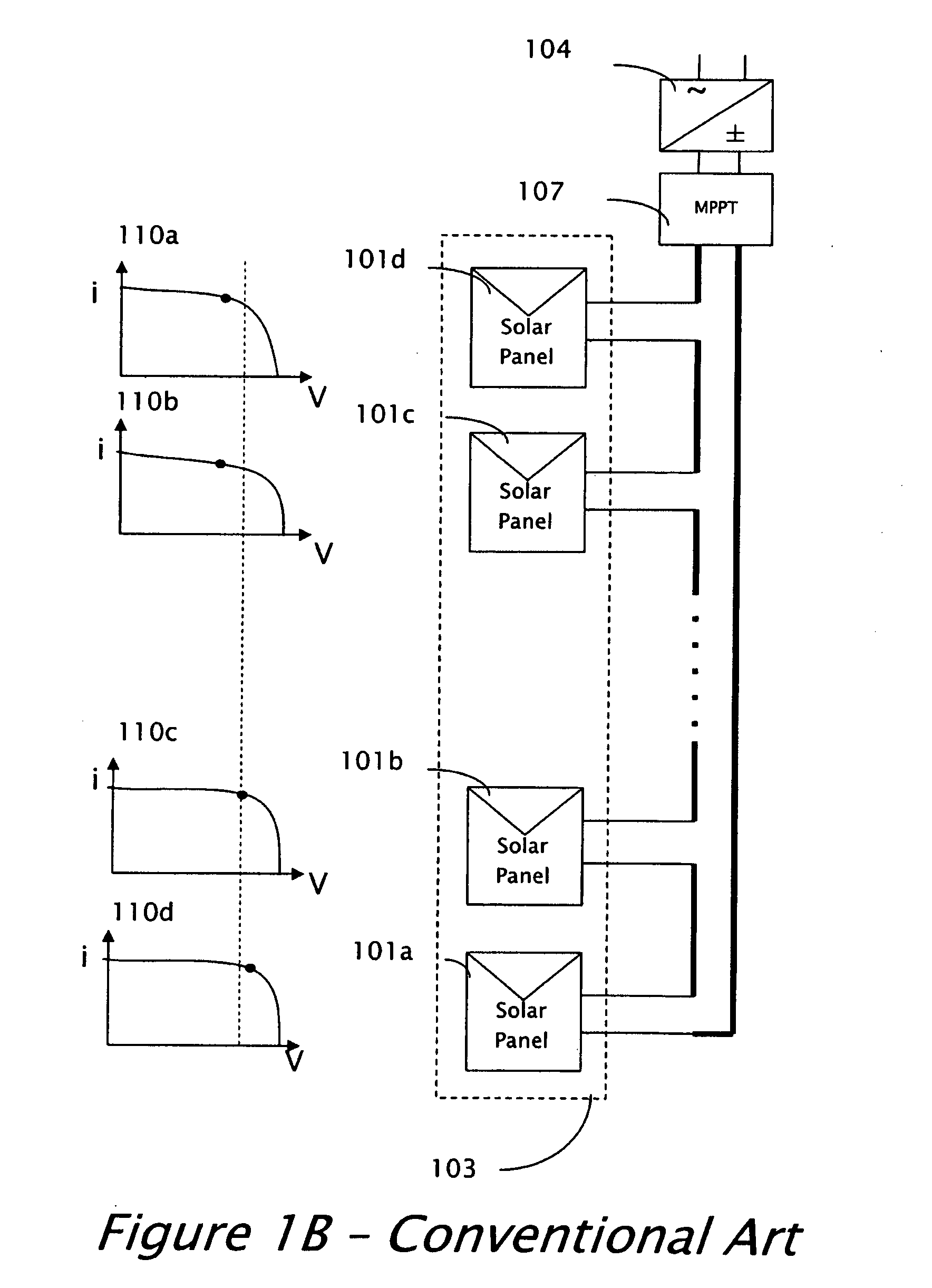
A problem facing the solar array designer is to produce a standard AC current at 120V or 220V root-mean-square (RMS) from a combination of the low voltages of the solar panels.
The delivery of high power from a low voltage requires very high currents, which cause large conduction losses on the order of the second power of the current i2.
Consequently, the arrangement is not operated at best achievable efficiency.

Method used


Image

  • Parallel connected inverters
  • Parallel connected inverters
  • Parallel connected inverters

Examples


Embodiment Construction

[0026]Reference will now be made in detail to embodiments of the present invention, examples of which are illustrated in the accompanying drawings, wherein like reference numerals refer to the like elements throughout. The embodiments are described below to explain the present invention by referring to the figures.

[0027]It should be noted, that although the discussion herein relates primarily to photovoltaic systems and more particularly to those systems previously disclosed in U.S. application Ser. No. 11 / 950,271, the present invention may, by non-limiting example, alternatively be configured as well using conventional photovoltaic distributed power systems and other distributed power systems including (but not limited to) wind turbines, hydroturbines, fuel cells, storage systems such as battery, super-conducting flywheel, and capacitors, and mechanical devices including conventional and variable speed diesel engines, Stirling engines, gas turbines, and micro-turbines.

[0028]By way ...


PUM


Abstract

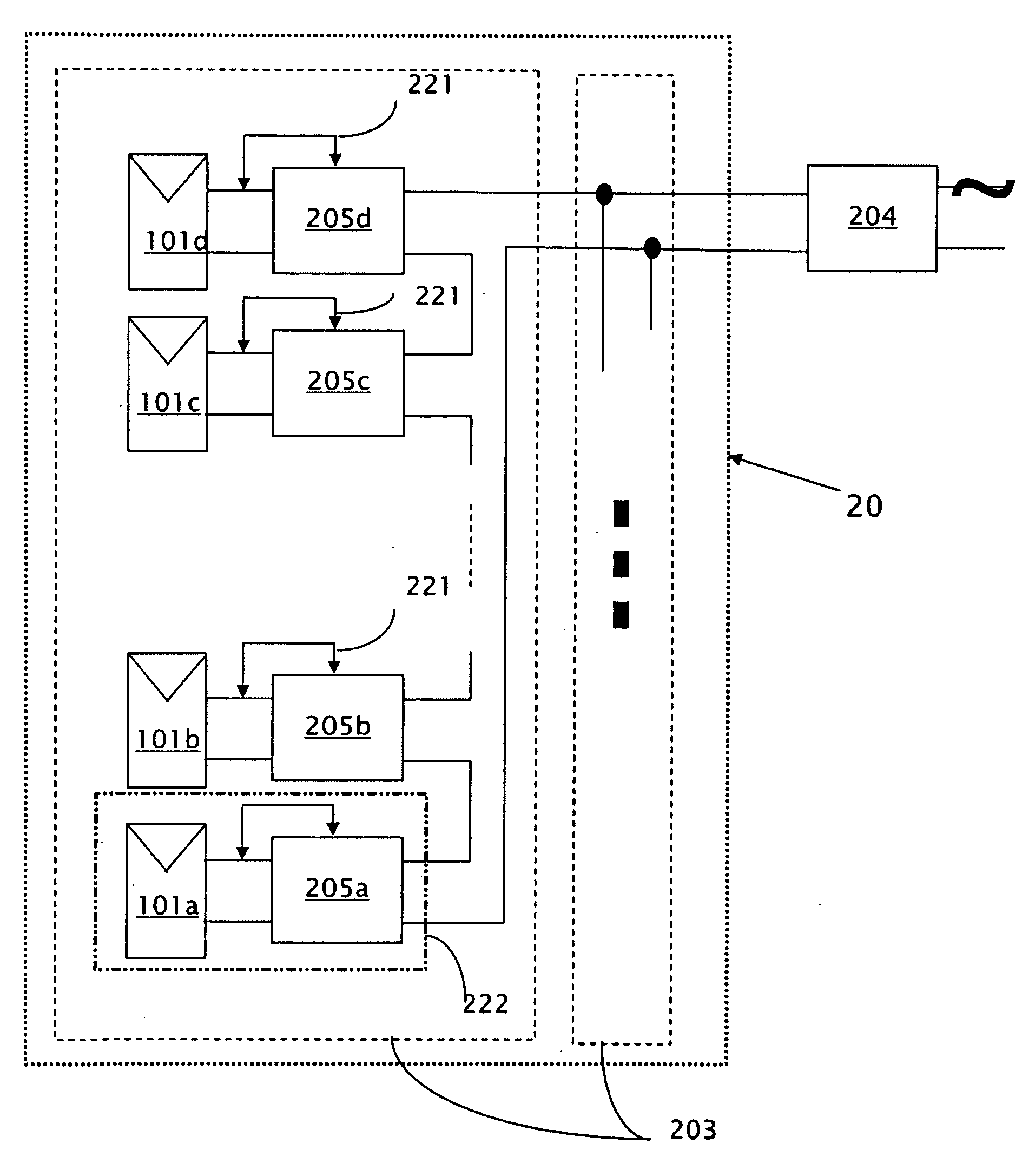
A distributed power system wherein a plurality of power converters are connected in parallel and share the power conversion load according to a prescribed function, but each power converter autonomously determines its share of power conversion. Each power converter operates according to its own power conversion formula / function, such that overall the parallel-connected converters share the power conversion load in a predetermined manner.

Description

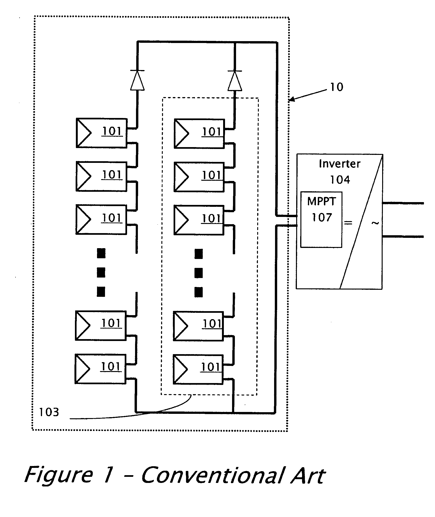
CROSS REFERENCE TO RELATED APPLICATIONS[0001]The present application claims priority benefit from U.S. Application Ser. No. 60 / 992,589, filed on Dec. 5, 2007, the disclosure of which is incorporated herein by reference in its entirety.TECHNICAL FIELD[0002]The present invention relates to distributed power systems and, more particularly, a system and method for sharing power inversion / conversion between parallel connected power inverters / converters connected to the distributed power system.DESCRIPTION OF RELATED ART[0003]A conventional installation of a solar distributed power system 10, including multiple solar panels 101, is illustrated in FIG. 1. Since the voltage provided by each individual solar panel 101 is low, several panels 101 are connected in series to form a string 103 of panels 101. For a large installation, when higher current is required, several strings 103 may be connected in parallel to form overall system 10. The interconnected solar panels 101 are mounted outdoors...

Claims


Application Information

Patent Timeline
IPC IPC(8): H02M7/44H02M1/00H02M7/493
CPCG01S3/7861H02J3/46H02M7/44Y02E10/58H02M7/493H02J2300/10H02J2300/26H02J3/381Y02E10/56H02M1/0077H02J3/388Y02E10/52
Inventor ADEST, MEIRSELLA, GUYHANDELSMAN, LIORGALIN, YOAVFISHELOV, AMIRGAZIT, MEIRGLOVINSKI, TZACHIBINDER, YARON
Owner SOLAREDGE TECH LTD
Learn More