
Grommet for cables

a cable and grommet technology, applied in the direction of electrical equipment, multi-purpose tools, insulating bodies, etc., can solve the problems of not widely used flame retardant materials, and achieve the effect of enhancing the effectiveness of brushes, preventing significant air leakage, and facilitating the passage and removal of cabling

Inactive Publication Date: 2009-06-18
AQUILA INC
View PDF46 Cites 48 Cited by
  • Summary
  • Abstract
  • Description
  • Claims
  • Application Information

AI Technical Summary

Benefits of technology

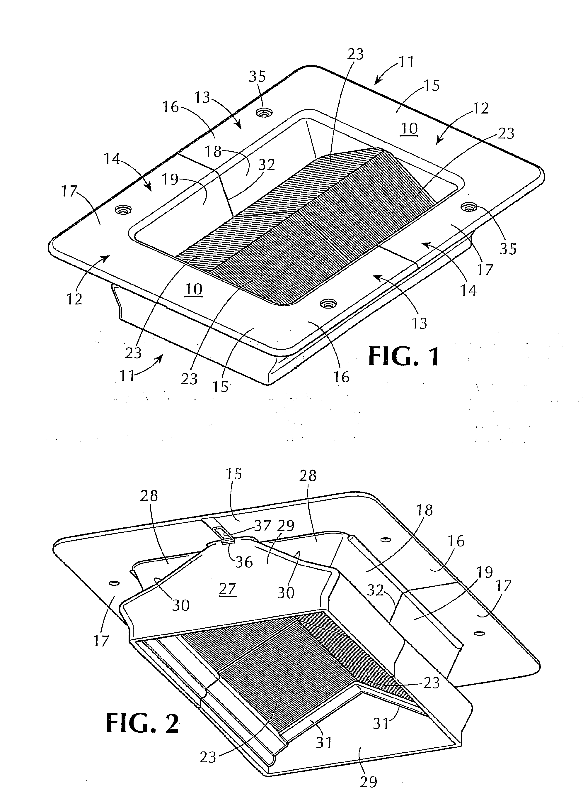
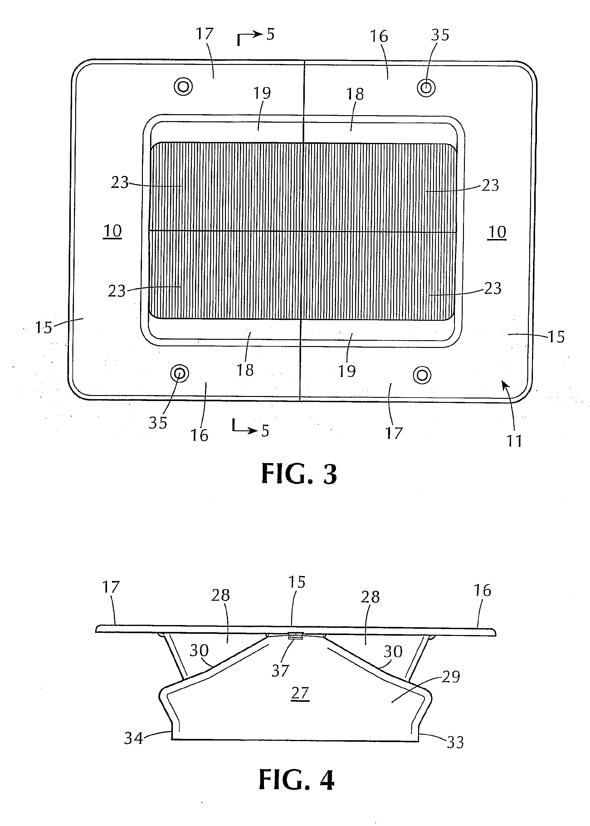
[0009]According to one aspect of the invention, the side sections of the U-shaped grommet-forming end units are formed with channels for reception of brushes provided with cantilever mounted bristles. The brushes are mounted at an acute angle of about 30 degrees to a plane defined by peripheral mounting flanges of the end units. A pair of brushes extend from opposite sides of the end unit and meet mid-way to provide effective sealing against significant air leakage from one side of the brush pair to the other, while readily accommodating the easy passage and removal of cabling. By mounting the brushes at an angle of around 30 degrees, the effectiveness of the brushes is enhanced, and the effective length of the brushes may be increased within a grommet opening of a given width. In the illustrated and preferred embodiments of the invention, the brush filaments extend upwardly from their cantilever mountings. However, in appropriate cases the brush filaments could be extended downward at an acute angle.
[0011]The invention provides for a versatile set of grommet-forming components that can be manufactured and installed on an economical and flexible basis to enable data centers and the like to operate with a desired high level of cooling efficiency. The grommet system of the invention, while particularly advantageous for use in high density data centers, can also be employed to great advantage in other venues, such as offices incorporating raised flooring structures for the passage of wires and cables and, in many cases also forming an enclosure for HVAC air.

Problems solved by technology

Heretofore, such flame retardant materials have not been widely used, because they tend to lack conductivity, which is important for dissipating static electric charges developed in and around the brush elements and around the cabling passing through the brush elements.

Method used


Image

  • Grommet for cables
  • Grommet for cables
  • Grommet for cables

Examples


Embodiment Construction

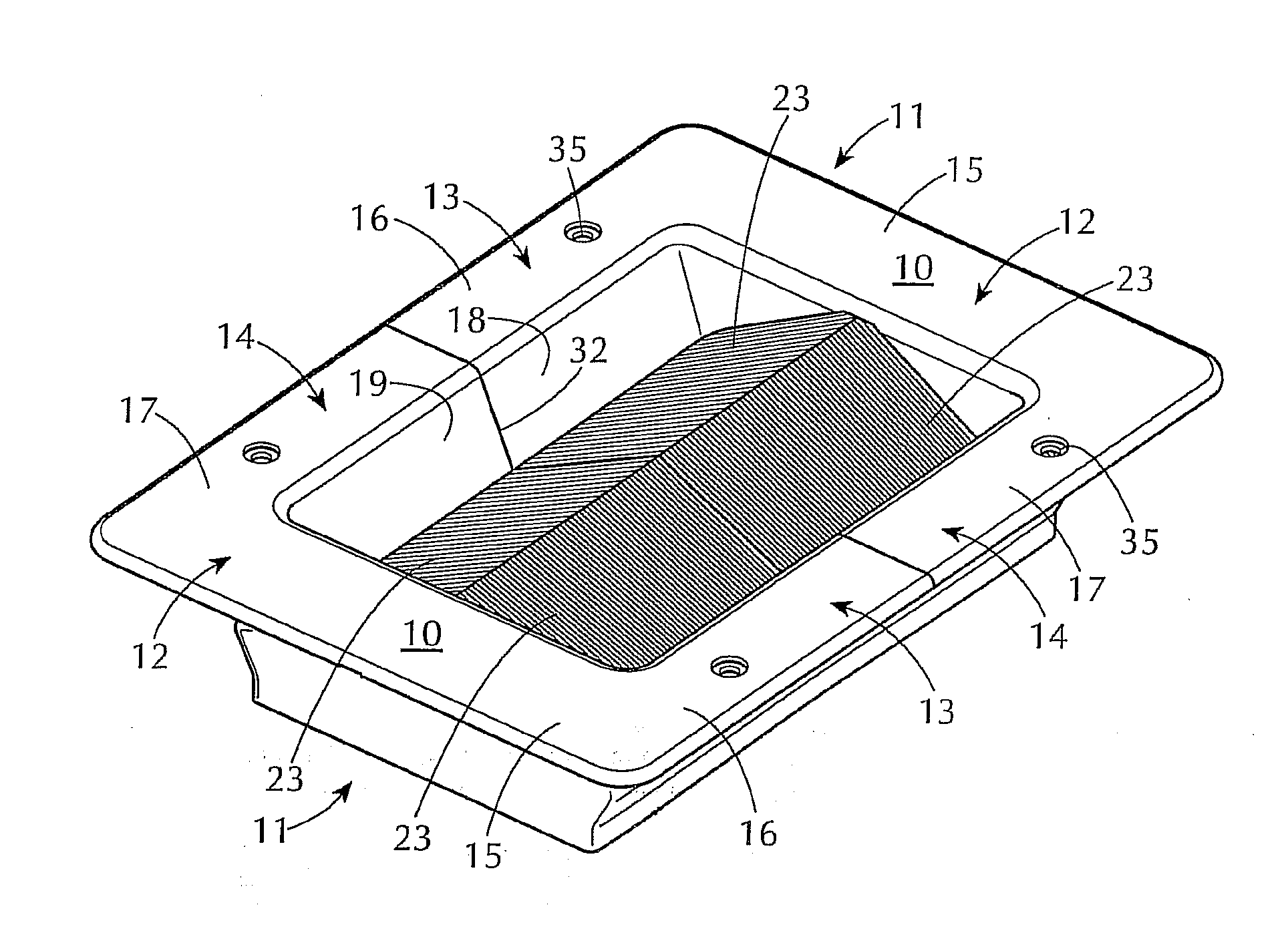
[0028]Referring now to the drawings, the reference numeral 10 designates generally a basic grommet-forming end unit according to the invention. The end unit comprises a frame 11 of generally U-shaped configuration, comprising an end section 12 and spaced-apart, opposed side sections 13, 14. The entire frame, consisting of the sections 12-14, advantageously is a unitary molding of structural plastic material, and particularly a plastic material having fire retardant characteristics. A preferred form of such material, for example, is available from GE Plastics, under their trademark “CYCOLAC”, and particularly Cycolac Resin FR23. This product is a flame retardant ABS, which is desirable for the purposes of this invention.

[0029]The end and side sections 12-14 of the end unit 10 are formed with laterally extending flanges 15-17, which define a flat plane and provide means for supporting and securing the end unit 10 on a panel (not shown) having an opening therein. The panel most typical...


PUM

PropertyMeasurementUnit
acute angleaaaaaaaaaa
sizeaaaaaaaaaa
angleaaaaaaaaaa

Abstract

A cable grommet system for installation in data centers, offices and the like, for sealing cable openings in raised flooring, wall or ceiling panels, server cabinets, etc. to facilitate the installation and revision of wiring and cabling to server installations while minimizing losses of any provided conditioned air. A wide variety of grommet configurations is possible with a limited number of component parts. An advantageous acute angle mounting of sealing brushes enhances the sealing effectiveness thereof, particularly for smaller sizes of cable openings. In some embodiments, a novel arrangement of electrical conductors is incorporated into the grommet structures for dissipation of electrostatic charges, enabling the basic frame components to be formed of a flame retardant material.

Description

RELATED APPLICATION[0001]This is a divisional of U.S. patent application Ser. No. 11 / 865,269, filed Oct. 1, 2007.BACKGROUND OF THE INVENTION[0002]This invention relates to a cable grommet system, particularly for use in connection with data centers, offices and the like to accommodate the passage of cables from one side to another of a floor, cabinet, rack, or other enclosure serving as a containment between two areas, particularly where the areas are under unequal air pressure, such as for conditioned air (heating or cooling) under positive pressure. The term “cable”, as used herein, refers not only to flexible electrical wires and cables but also to rigid elements, such as pipes, conduits and the like that may be extended through openings in floor or other panels, especially where it is desired to restrict the flow of air through such openings.[0003]In data centers and the like, large numbers of computer servers typically are arranged in a compact configuration of cabinets or rack...

Claims


Application Information

Patent Timeline
Patent Type & Authority Applications(United States)
IPC IPC(8): H01B17/38
CPCH02G3/185Y10T16/05Y10T16/063H02G3/22
Inventor SEMPLINER, ARTHUR T.MARCHANT, BERKELEY T.
Owner AQUILA INC
Learn More