Electric power conservation system

a technology of electric power conservation and power supply, applied in the direction of relays, emergency power supply arrangements, pulse techniques, etc., can solve the problems of prohibitively expensive systems, unattractive aesthetics, and extensive installation costs, and achieve the effect of reducing the amount of utility power usage and reducing load

Active Publication Date: 2009-06-18
EVANS SR BRUCE JONATHAN
View PDF18 Cites 11 Cited by
  • Summary
  • Abstract
  • Description
  • Claims
  • Application Information

AI Technical Summary

Benefits of technology

[0023]The invention is an electric power conservation system connected between an AC utility power source and a load circuit. The electric power conservation system includes a DC rechargeable energy source, an energy charger component, an inverter unit for changing the stored DC energy into AC power, a method to deactivate and reactivate the system's active components as the availability of utility power dictates, a bypass method to disconnect the electric power conservation system's active components from the load circuit and to connect the utility power directly to the load circuit; in the event that it would be necessary, a monitor and control method to optimize utility power usage, and circuitry necessary for supplying electric power derived from both sources; the available utility power; and the stored inverted power, to the load circuit. During normal operations when normal AC utility power is available, and the bypass is not engaged, the load circuit

Problems solved by technology

Examples are, solar panel systems and wind powered systems, which require an extensive amount of labor to install, and are aesthetically unattractive.
Consequently, such systems are prohibitively expensive.
Currently, the national electrical grid is being utilized nearly to its maximum capacity, and the co

Method used


Image

  • Electric power conservation system
  • Electric power conservation system
  • Electric power conservation system

Examples


Embodiment Construction

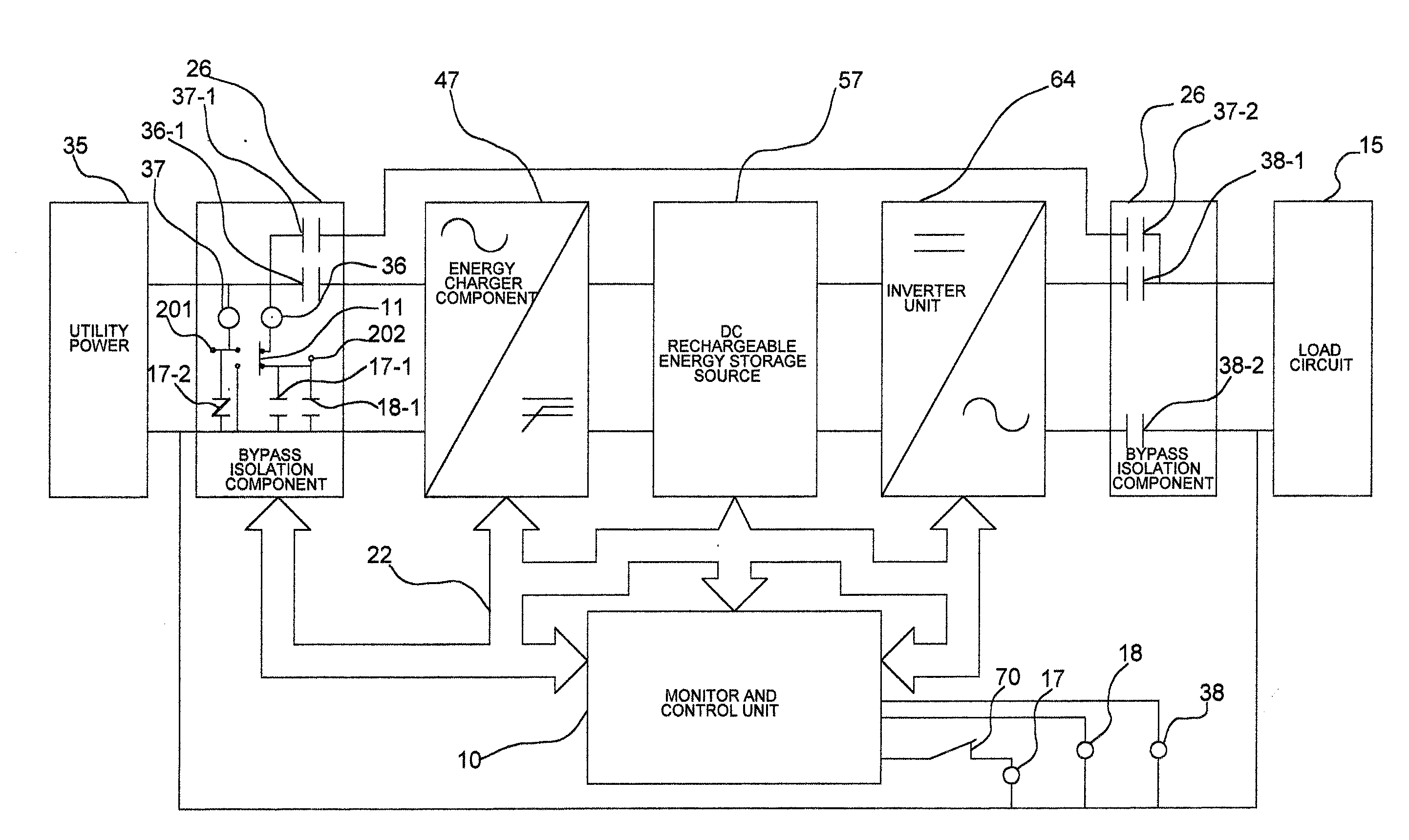
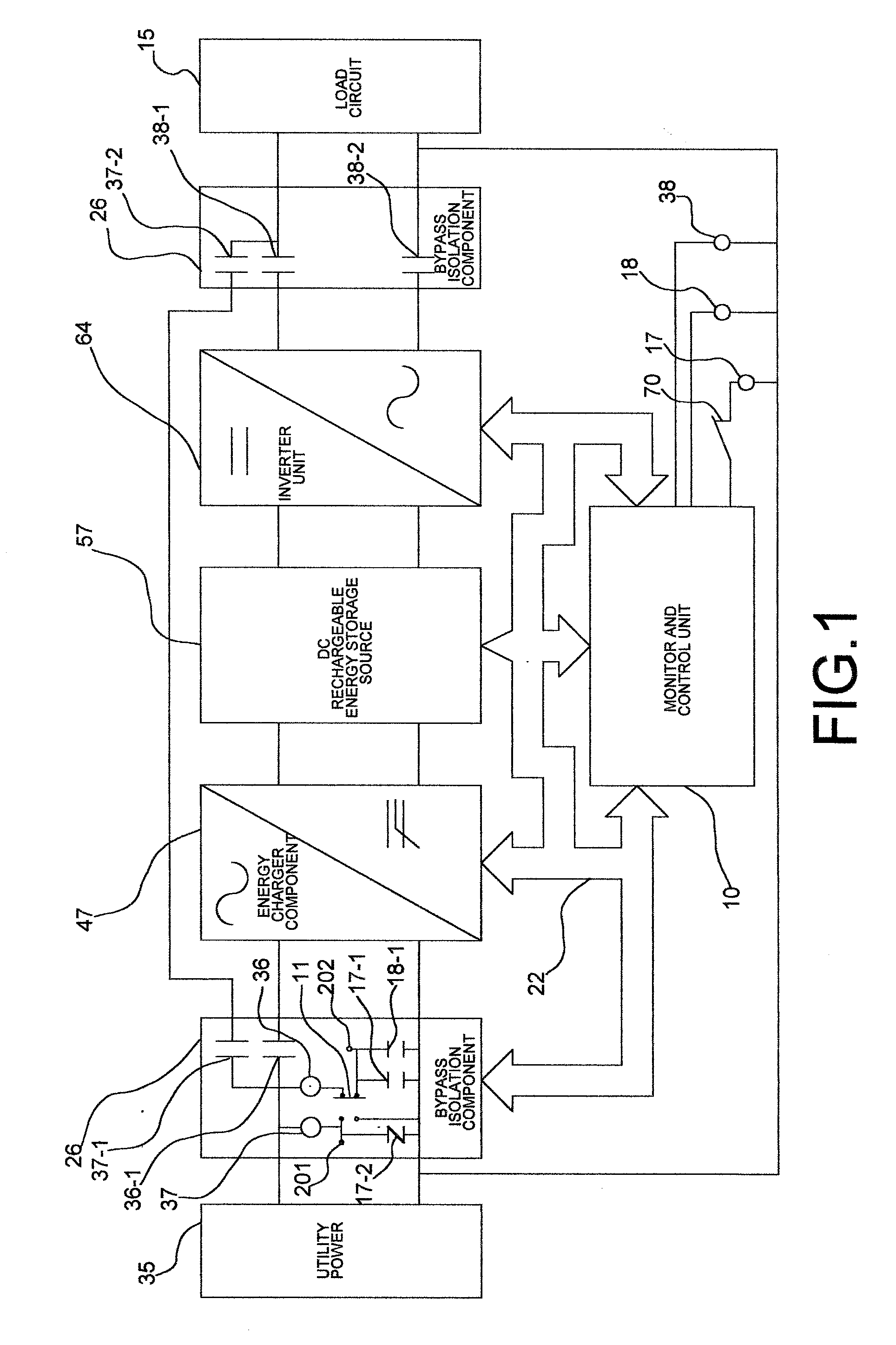
[0038]FIG. 1 schematically illustrates an electric power conservation system in accordance with the principles of the present invention, showing a utility power source 35 supplying 120 VAC electrical power to a load circuit 15 through separate current paths, a bypass current path, and an energy conservation current path. The electric power conservation system can automatically and manually switch between the bypass current path and the energy conservation current path. When the energy conservation current path is active, the demand of the load circuit 15 causes currents of different magnitudes to flow in a energy charger component 47, a DC rechargeable energy source 57, and an inverter unit 64 that are connected in series. As will be seen in the following paragraphs, the electric power conservation system is designed to minimize the amount of power supplied by the utility power source 35 and maximize the power supplied by the DC rechargeable energy source 57 that is included in the ...


PUM


Abstract

An electric power conservation system to be used between an AC utility power source and a load circuit in a home or business. The electric power conservation system comprises an energy charger component, a DC rechargeable energy source, an inverter unit, a bypass isolation circuit, a monitor and control unit, coil contactors and contacts, and necessary circuitry for supplying a load circuit with the power it requires. The invention reduces consumption of electric power from public utility companies, thereby decreasing the load on the national electrical grid. Where utility companies offer lower off-peak rates to consumers of electrical power, it becomes exceedingly desirable to have such a system in place, to save consumers money. During normal operations wherein normal utility power is available, the load circuit derives part of its power from the AC utility power source, and the remaining power that it requires from the electric power conservation system.

Description

CROSS REFERENCE TO RELATED APPLICATION[0001]This application is based on and claims the benefit of Provisional Patent Application Ser. No. 60 / 996,955, filed Dec. 12, 2007, which is incorporated herein by reference.BACKGROUND OF THE INVENTION[0002]1. Field of the Invention[0003]The present invention relates to an electric power conservation system, and more specifically, how a system comprised of a DC rechargeable energy source, an energy charger component, an inverter unit, a bypass isolation circuit, and a monitor and control unit can be configured to supply a load circuit, located in industrial, commercial, and residential dwellings, with the power that is required and demanded, while conserving the power supplied by an AC utility power source. Also, a cost savings can be experienced by industrial, commercial and residential users of electric power. When utility companies offer off-peak rates to consumers of electrical power, it becomes exceedingly desirable to have such a system ...

Claims


Application Information

Patent Timeline
IPC IPC(8): H02J3/00
CPCH02J7/34H02J3/32
Inventor EVANS, SR., BRUCE JONATHAN
Owner EVANS SR BRUCE JONATHAN
Why Eureka
Try Eureka