Capacitor and method of manufacturing the same

a technology of capacitors and dielectric components, applied in the direction of capacitors, fixed capacitor details, coatings, etc., can solve the problems of affecting the quality of capacitors, etc., and achieving the effect of reducing the number of components and reducing the number of parts

Active Publication Date: 2009-06-18
TAIYO YUDEN KK
View PDF1 Cites 18 Cited by
  • Summary
  • Abstract
  • Description
  • Claims
  • Application Information

AI Technical Summary

Benefits of technology

[0007]Therefore, an object of at least one of the disclosed embodiments of the present invention is to provide a capacitor and a capacitor manufacturing method that can enhance capacitance density although it is compact, and a method of manufacturing the capacitor. Furthermore, at least one of the disclosed embodiments of the present invention has another object to provide a capacitor and a capacitor manufacturing method that can simplify a manufacturing process and reduce ESL.
[0009]In the capacitor according to an embodiment of the present invention, the pair of substantially comb-shaped surface electrodes are formed on the surface of the dielectric material that is formed of anodic metal oxide and has a predetermined thickness so that the comb-shaped portions thereof are arranged alternately and in parallel so as to be spaced from one another at predetermined intervals. In addition, the capacitor is provided with the plural substantially columnar (pillar-shaped) internal electrodes whose one ends are connected to the comb-shaped portions and whose other ends extend in the thickness direction of the dielectric material. Therefore, the area which determines the capacitance of the capacitor can be increased and thus the capacitance can be increased.
[0010]Furthermore, with respect to the respective internal electrodes connected to the different surface electrodes, the current directions thereof are opposite to each other, and thus the effect of offsetting magnetic field is enhanced, and thus ESL can be reduced.
[0012]According to one or more of the disclosed embodiments of this invention, the manufacturing process of filling electrode materials into pores after the pores are formed in the dielectric material can be simplified.

Problems solved by technology

The Al electrolytic capacitors have a problem that liquid leak, etc. occurs due to use of electrolytic liquid, etc.
Furthermore, the laminated ceramic capacitors require a burning step, and thus it induces thermal shrinkage between an electrode and a dielectric member, etc.
However, the background art described above has the following problems.
Therefore, it is difficult to increase the aspect ratio in the z direction (thickness direction).
Furthermore, in the technique disclosed in JP-T-2006-512787, it is also difficult to increase the aspect ratio in the z direction because the electrode is also formed by etching.
As described above, in the electrode forming technique using etching, it is difficult to increase the aspect ratio in the z direction of the electrode portion in order to increase the area defining the capacitance.

Method used


Image

  • Capacitor and method of manufacturing the same
  • Capacitor and method of manufacturing the same
  • Capacitor and method of manufacturing the same

Examples


Embodiment Construction

[0022]A preferred embodiment according to the present invention will be described hereunder with reference to the accompanying drawings. However, the preferred embodiment is not intended to limit the present invention. In the present disclosure where conditions and / or structures are not specified, the skilled artisan in the art can readily provide such conditions and / or structures, in view of the present disclosure, as a matter of routine experimentation.

[0023]First, a first embodiment according to the present invention will be described with reference to FIGS. 1 to 3.

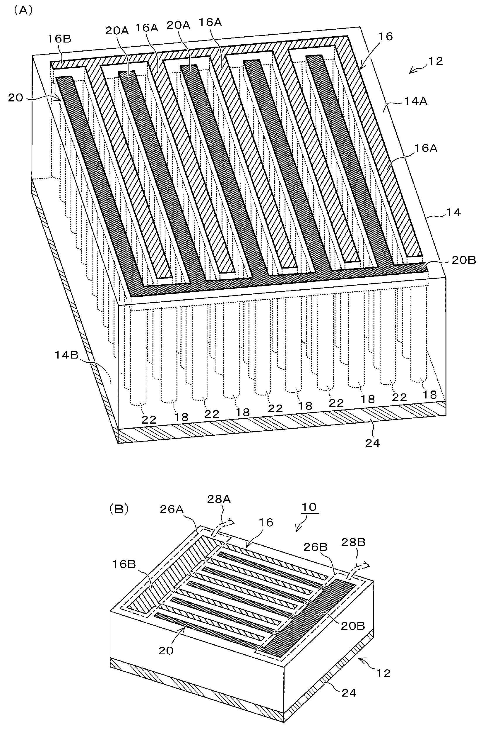
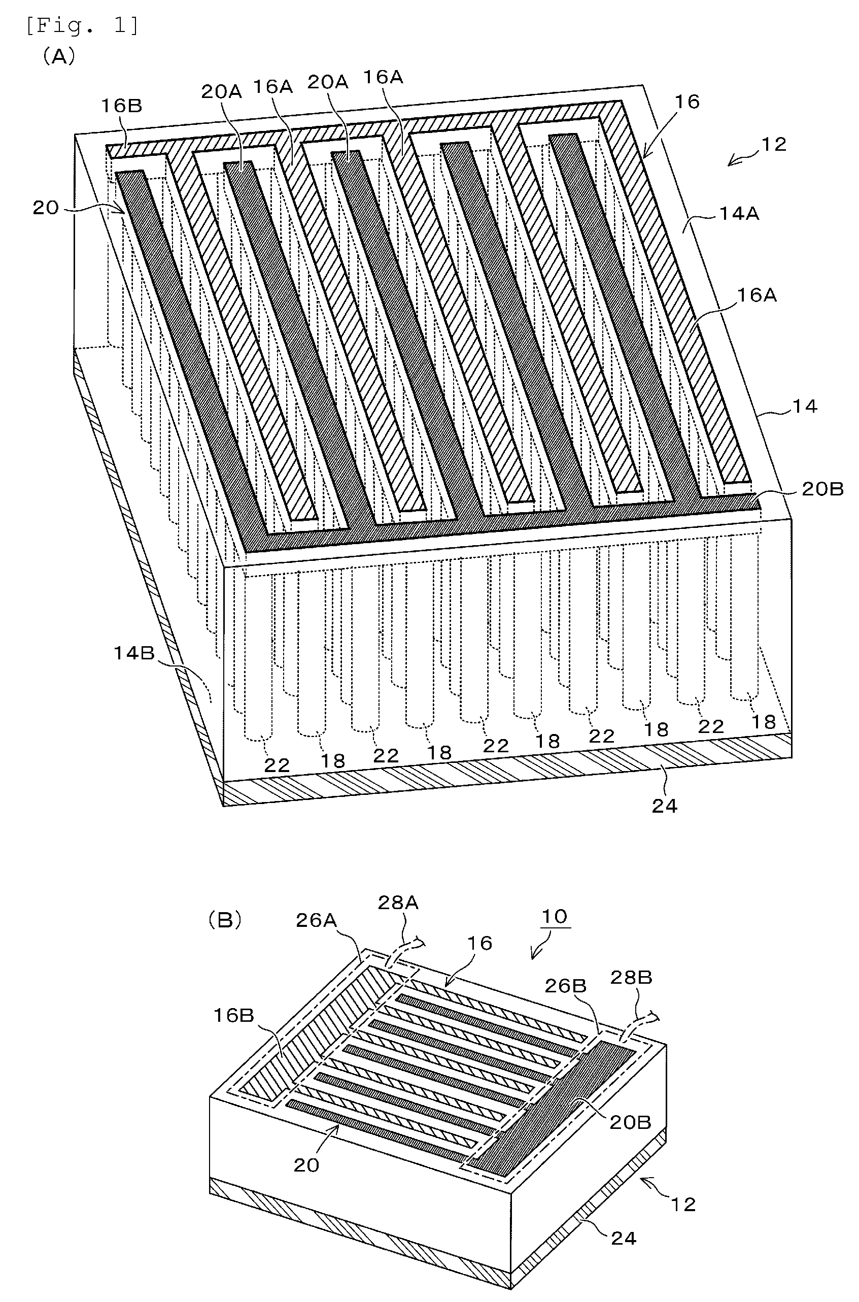
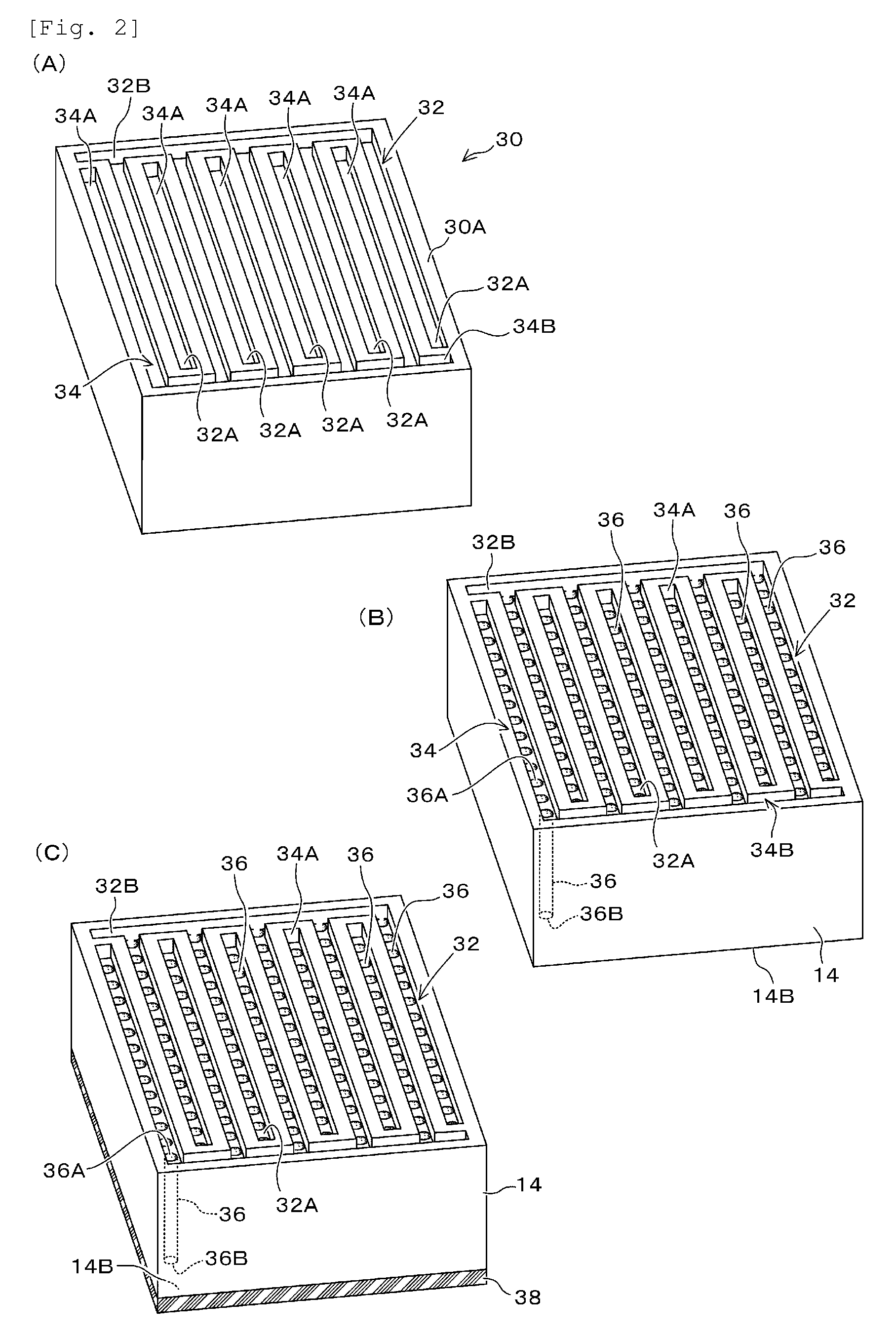
[0024]FIG. 1A is a perspective view showing the electrode construction of a capacitor element according to this embodiment, and FIG. 1B is a perspective view showing the outlook of the capacitor according to this embodiment. FIGS. 2 and 3 are diagrams showing examples of the manufacturing process of this embodiment.

[0025]As shown in FIG. 1, the capacitor 10 of this embodiment is mainly constructed by a capacitor elemen...


PUM


Abstract

A capacitor includes a dielectric material that is formed of anodic metal oxide; a pair of substantially comb-shaped surface electrodes formed on the same principal surface of the dielectric material; and plural substantially columnar internal electrodes whose one ends are connected to the respective comb-shaped portions of the pair of the surface electrodes and whose other ends extend in the thickness direction of the dielectric material.

Description

BACKGROUND OF THE INVENTION[0001]1. Field of the Invention[0002]The present invention relates to a capacitor and a method of manufacturing the same, and particularly to enhancement of capacity density, simplification of a manufacturing process and reduction of ESL (Equivalent Series Inductance).[0003]2. Description of the Related Art[0004]Al electrolytic capacitors and laminated ceramic capacitors are known as capacitors which are broadly used at present. The Al electrolytic capacitors have a problem that liquid leak, etc. occurs due to use of electrolytic liquid, etc. Furthermore, the laminated ceramic capacitors require a burning step, and thus it induces thermal shrinkage between an electrode and a dielectric member, etc. For example, as a technique of implementing a compact and large-capacitance capacitor is known a method of manufacturing laminated electrical parts shown in JP-A-9-45577, and a capacitor and a method of manufacturing the same disclosed in JP-T-2006-512787, for e...

Claims


Application Information

Patent Timeline
Patent Type & Authority Applications(United States)
IPC IPC(8): H01G4/002B05D5/12
CPCH01G4/005
Inventor MASUDA, HIDETOSHIKAWANO, KENJI
Owner TAIYO YUDEN KK
Why Eureka
Try Eureka