Cutting insert and tool for chip removing machining

a technology of cutting insert and cutting tool, which is applied in the field of chip removal machining, can solve problems such as weak cutting corners, and achieve the effect of improving the mutual support function

Active Publication Date: 2009-06-18
SECO TOOLS AB
View PDF7 Cites 34 Cited by
  • Summary
  • Abstract
  • Description
  • Claims
  • Application Information

AI Technical Summary

Benefits of technology

[0006]It is also desirable to improve the mutual support function between the cutting insert and the insert seal formed in the milling body.
[0007]It is also desirable that the cutting insert is given such a positioning in the cutting body that the cutting insert does not interfere with the machined surface that is obtained during milling using the tool according to the present invention.

Problems solved by technology

A disadvantage of these cutting inserts is that they have weak cutting corners.

Method used


Image

  • Cutting insert and tool for chip removing machining
  • Cutting insert and tool for chip removing machining
  • Cutting insert and tool for chip removing machining

Examples


Embodiment Construction

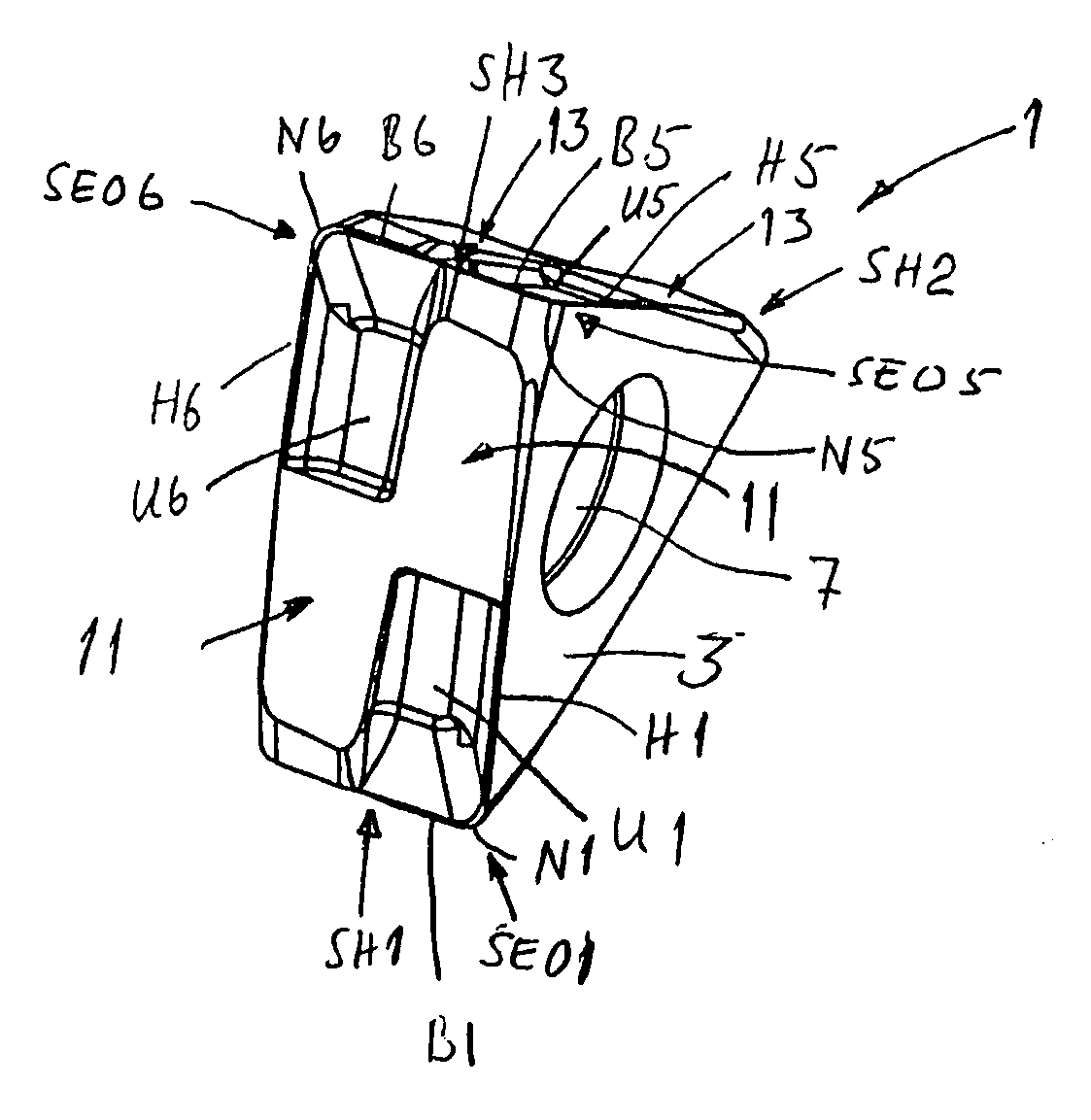
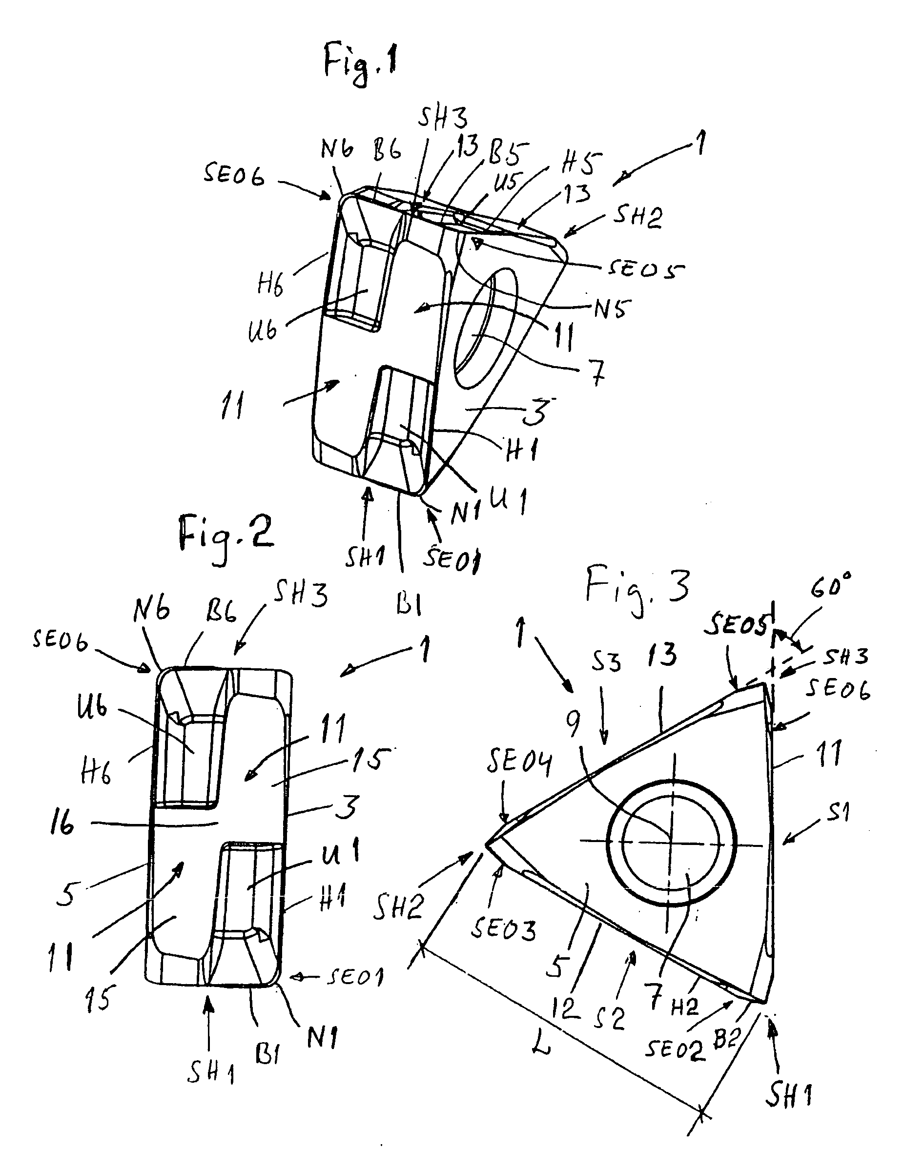
[0019]The cutting insert 1 according to the present invention shown in FIGS. 1-3 constitutes a milling insert, which is double-sided or indexable. The cutting insert has a triangular basic shape and is manufactured from pressed or injection moulded cemented carbide. With “cemented carbide” reference is here made to WC, TiC, TaC, NbC etc., in sintered combination with a binder metal, such as, for instance, Co or Ni. The cutting insert 1 is preferably at least partly covered with a layer of, e.g., Al2O3, TiN and / or TiCN. In certain cases, it may be justified that the cutting edges consist of soldered superhard materials such as CBN or PCD.

[0020]As is seen in FIG. 3, the cutting insert 1 has in planar view a generally triangular shape. The cutting insert 1 comprises three sides S1, S2 and S3 presenting three cutting corners SH1, SH2 and SH3 at intersections of the sides. The length of the side S2 has been designated L in FIG. 3 and the other sides S1 and S3 have the corresponding lengt...


PUM

PropertyMeasurementUnit
wedge anglesaaaaaaaaaa
setting angleaaaaaaaaaa
anglesaaaaaaaaaa

Abstract

An indexable milling insert having triangular shape, the cutting insert comprising a mounting hole placed centrally in the cutting insert, a first support surface and a second support surface, which support surfaces are parallel with each other and act as alternating support surfaces, that the cutting insert comprises three equally long sides, which extend between the parallel support surfaces, that the cutting insert is provided with main cutting edges, which are orientated perpendicularly to the center axis of the mounting hole as well as provided in such a way that a rotation of the cutting insert around the center of the mounting hole to an alternative insert scat alternatively a turning of the cutting insert to an alternative insert seat provides an identical location of the main cutting edges in relation to a piece to be machined, and that the wedge angles (β) of the cutting insert are in the range of 70°≦β≦85°. The invention also relates to a milling tool equipped with the milling inserts defined above. The cutting insert comprises planar support surfaces situated on the sides, and the support surfaces in the respective sides form mutual angles of 60°.

Description

BACKGROUND AND SUMMARY[0001]The present invention relates to the area of chip removing machining and then especially to a milling insert and a milling tool. The milling insert is indexably mounted in the milling tool. The milling tool is an end mill having 90° setting angle.[0002]Upon tangential mounting of trigon inserts in a milling body as in applicants WO2007149035, the insert seats formed in the milling body of the milling tool have a trigon shape adapted to the cutting insert, as seen in planar view of the insert scat. The trigon shape of the insert seats entails that certain of the flanks of the milling body that surround the cutting insert comprise relatively little material, i.e., the flanks become weak as for carrying the loads.[0003]So-called triangular cutting inserts are generally known. A disadvantage of these cutting inserts is that they have weak cutting corners.[0004]It is desirable to provide a cutting insert and a tool for chip removing machining of the kind defin...

Claims


Application Information

Patent Timeline
Patent Type & Authority Applications(United States)
IPC IPC(8): B26D1/00
CPCB23C5/06B23C5/202B23C2200/0477B23C2200/085Y10T407/23B23C2200/367B23C2210/0407Y10T407/235B23B2200/3681B23C2200/087B23C2200/326B23C5/205B23C5/2204
Inventor JANSSON, MIKAEL
Owner SECO TOOLS AB
Why Eureka
Try Eureka