Self-fitting device for location in an ear canal

Inactive Publication Date: 2009-07-09
KIMBERLY-CLARK WORLDWIDE INC
View PDF21 Cites 84 Cited by
  • Summary
  • Abstract
  • Description
  • Claims
  • Application Information

AI Technical Summary

Problems solved by technology

The need for adequate hearing protection in high noise environments has long been recognized among those concerned with health and safety issues, and much effort has gone into providing such protection.
However, most experts in this field would acknowledge that this effort has not been very successful.
Protective devices have proliferated yet remained mediocre in performance.
Workers in high noise environments who should use these devices often do not, or use them only under duress from their employers.
The lack of worker compliance with safety rules is exacerbated by the fact that currently available hearing protection devices are often uncomfortable, clumsy to use, and / or perform poorly.
For example, existing disposable foam ear plugs are uncomfortable for wearers with small ear canals, and are difficult to properly insert.
This method can cause discomfort for people with small ear canals in that the more compressed the ear plug, the greater its exerted force toward re-expansion.
If this step is not done, or is insufficiently done, the ear plug is often inserted improperly so as to not provide optimal protection.

Method used


Image

  • Self-fitting device for location in an ear canal
  • Self-fitting device for location in an ear canal
  • Self-fitting device for location in an ear canal

Examples


Embodiment Construction

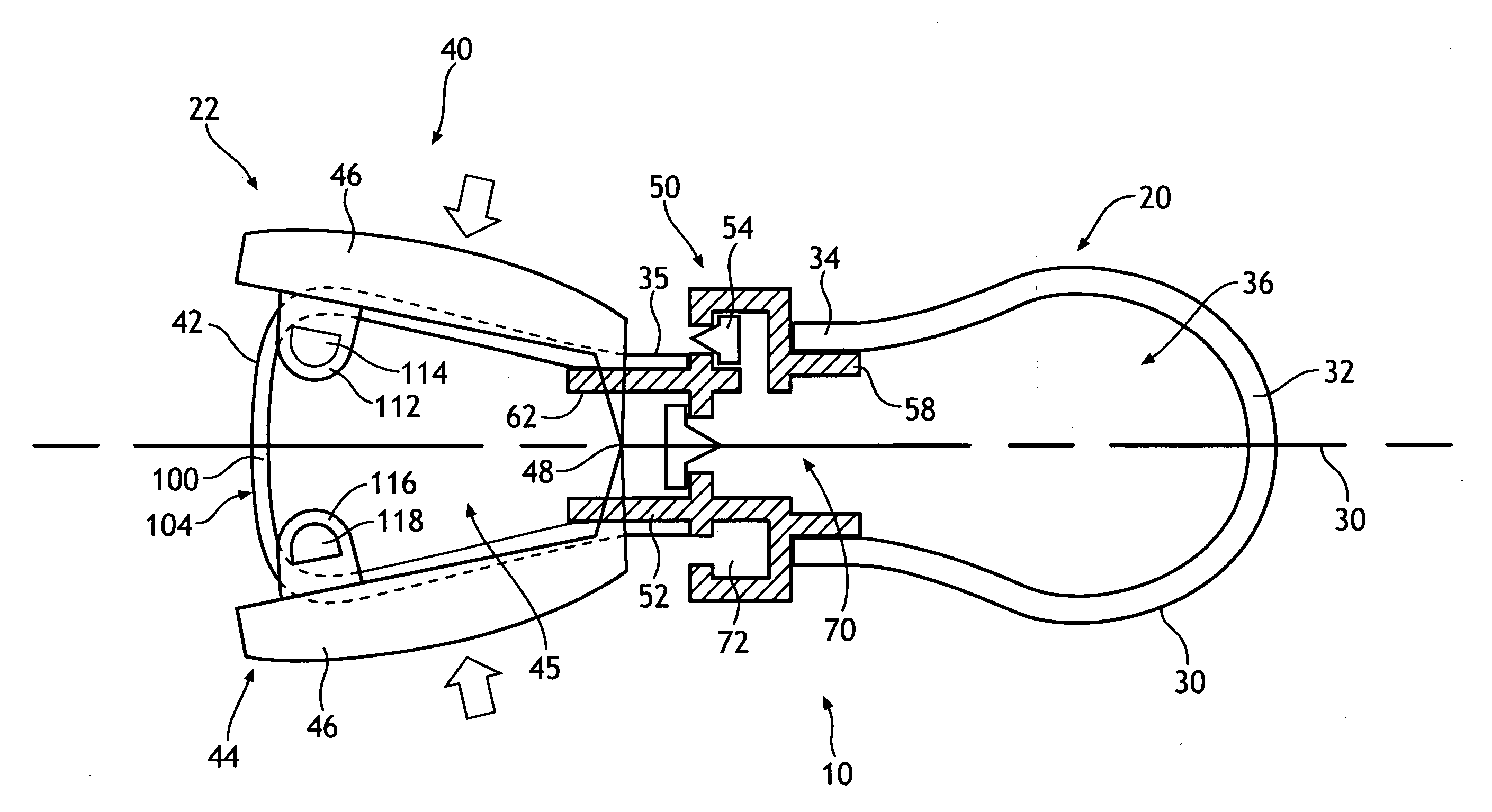
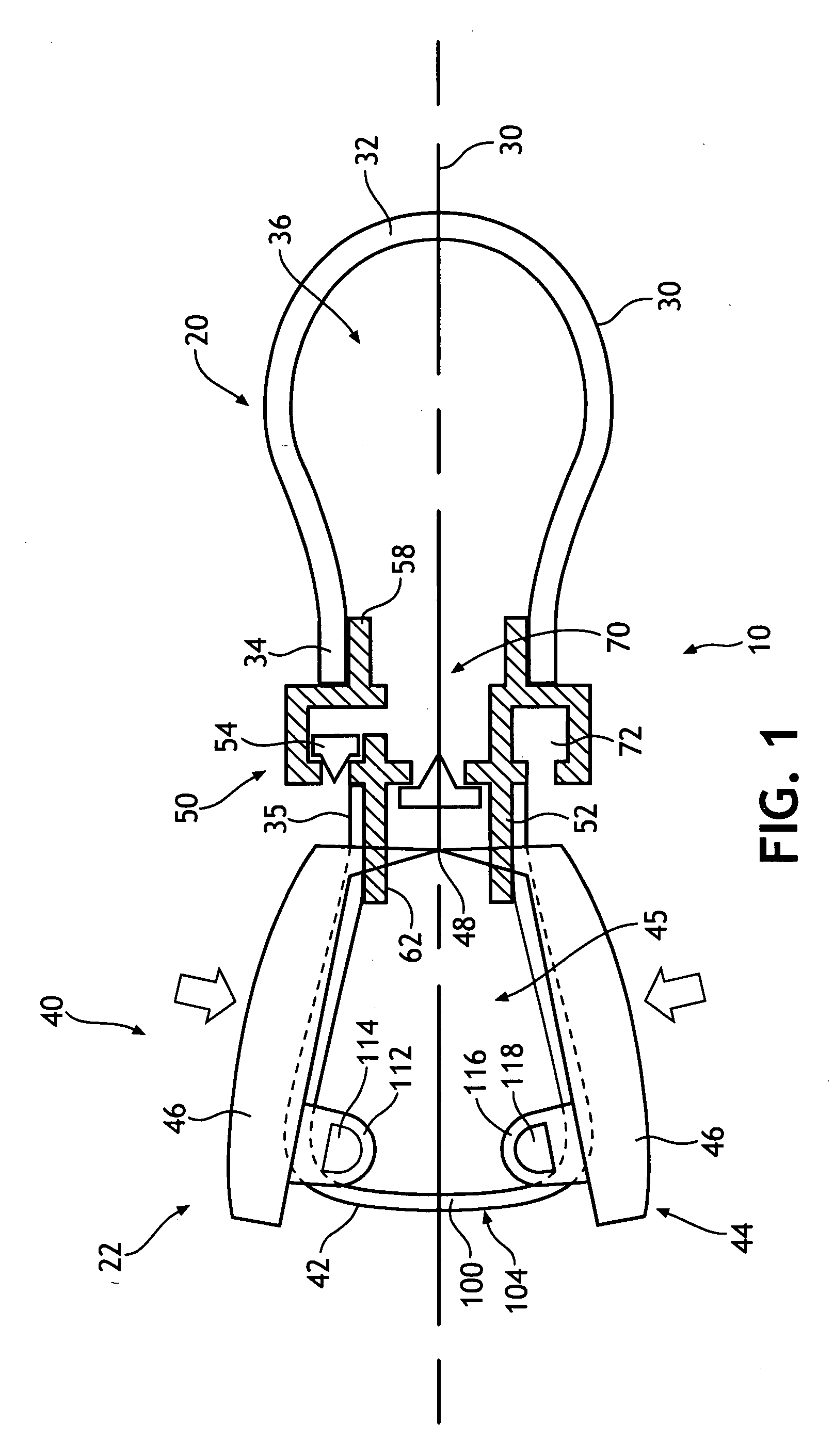
[0024]Referring now to the drawings, and in particular FIGS. 1-3, there is depicted a self-fitting device 10 for location in an ear canal 12. The device 10 has a body ear end 20, and a body user end 22. In particular, in FIG. 3, shown is a device 10 inserted into an outer ear 13 which is joined to the ear canal (not seen). Body ear end 20 includes a bladder 30, connected to the body user end 22 which includes a pump assembly 40. The body user end further includes a valve assembly 50, which serves to connect bladder 30 to pump assembly 40. The valve assembly 50 includes a central valve 52 and a side valve 54 which together, facilitate a predetermined pressure within the bladder 30 after the device 10 has been inserted into an ear canal and subsequently activated.

[0025]Desirably, the bladder 30 is resilient. Bladder 30 includes two main wall portions, a main body 32 and a collar portion 34 that are desirably, integrally connected together. For example, these two parts could be formed ...


PUM


Abstract

Self-fitting device for location in ear canal and related method, including a bladder joined with a pump assembly via a valve assembly. The pump assembly transfers air to the bladder and achieves a predetermined pressure with the chamber regardless of ear canal size. The predetermined pressure may be achieved by reducing excess air pressure through the valve assembly.

Description

BACKGROUND OF THE INVENTION[0001]The present invention relates generally to devices for location in an ear canal, and more particularly to such devices being self-fitting and used for sound optimization such as noise reduction and / or acoustic enhancement.[0002]The need for adequate hearing protection in high noise environments has long been recognized among those concerned with health and safety issues, and much effort has gone into providing such protection. However, most experts in this field would acknowledge that this effort has not been very successful. Protective devices have proliferated yet remained mediocre in performance. Workers in high noise environments who should use these devices often do not, or use them only under duress from their employers. Individuals that work in high noise environments rarely understand that the effects of high noise exposure are not limited to the moment but are cumulative as well. The lack of worker compliance with safety rules is exacerbated...

Claims


Application Information

Patent Timeline
IPC IPC(8): A61F11/10A61F11/00
CPCA61F11/10
Inventor PURCELL, RICKY WAYNEWELCHEL, DEBRA N.DREW, ROBERT A.JENKINS, SHAWN E.KRUEGER, JEFFREY JENNINGS
Owner KIMBERLY-CLARK WORLDWIDE INC
Why Eureka
Try Eureka