
Fundus camera

a camera and fundus technology, applied in the field offundus cameras, can solve the problems of difficult and it is not possible to obtain a favorable fundus imag

Inactive Publication Date: 2009-07-16
NIDEK CO LTD
View PDF6 Cites 15 Cited by
  • Summary
  • Abstract
  • Description
  • Claims
  • Application Information

AI Technical Summary

Benefits of technology

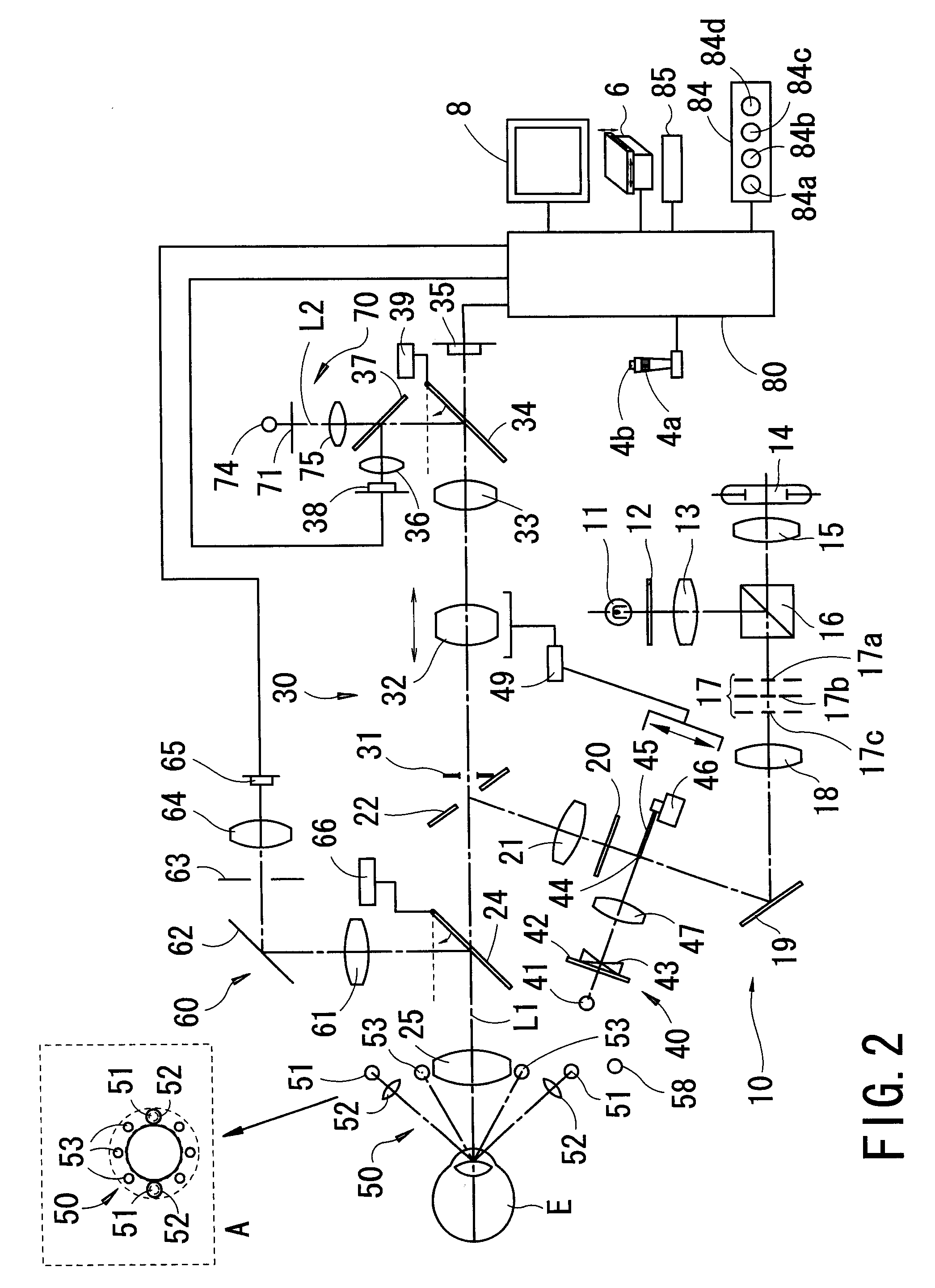
The invention is a fundus camera that can capture images of an examinee's eye. It includes a photographing optical system with a visible light source, a focusing lens, and an image pickup element. Additionally, there is a focus detection optical system with a first photodetector to determine the focus state of the photographing optical system. The camera also has a blink sensor with a second photodetector to detect blinking of the examinee's eye. The control unit of the camera suspends photographing when a blink is detected and controls the light source to emit illumination light after a predetermined period of time has passed. The technical effect of this invention is to improve the quality and efficiency of fundus photography by automatically detecting and addressing blinking and focus state issues.

Problems solved by technology

It is difficult to obtain a favorable fundus image by performing the photographing in such a state.
In addition, it is not possible to obtain a favorable fundus image if the examinee's eye blinks at the time of the photographing.

Method used


Image

  • Fundus camera
  • Fundus camera
  • Fundus camera

Examples


Embodiment Construction

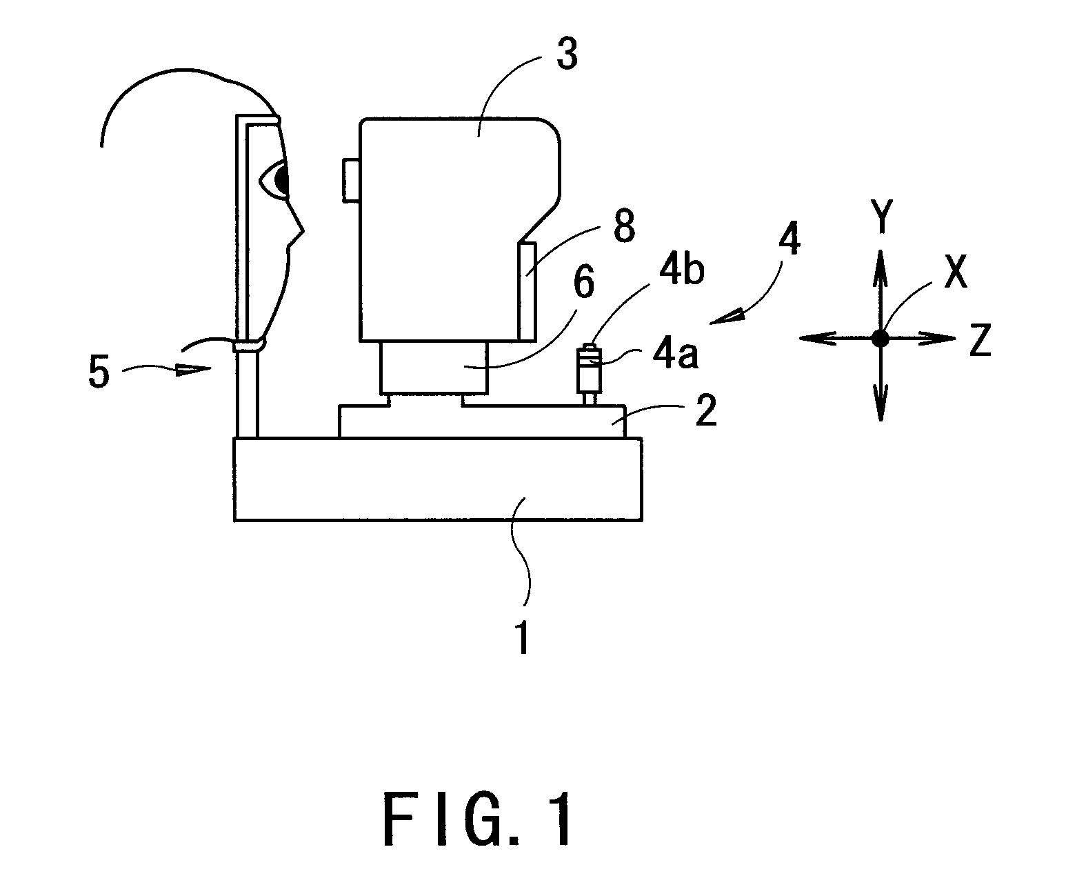
[0024]A detailed description of one preferred embodiment of a fundus camera embodied by the present invention is provided below with reference to the accompanying drawings. FIG. 1 is a schematic external view of the fundus camera according to the preferred embodiment of the present invention.

[0025]The fundus camera comprises a base 1, a mobile base 2 movable in a right / left direction (i.e., an X direction) and a back / forth direction (a working distance direction) (i.e., a Z direction) with reference to the base 1, a photographing unit (an apparatus main body) 3 three-dimensionally movable with reference to the mobile base 2 and housing an optical system to be described later, and a face (head) support unit 5 fixedly placed on the base 1 for supporting a face (a head) of an examinee. The photographing unit 3 is moved in the right / left direction, an up / down direction (i.e., a Y direction) and the back / forth direction with reference to an examinee's eye E by means of an XYZ driving uni...


PUM


Abstract

A fundus camera capable of favorably photographing a fundus of an examinee's eye comprises a fundus photographing optical system comprising a visible light source which emits illumination light onto the fundus, a focusing lens movable in an optical axis direction thereof, and a fundus image pickup element, an optical system comprising a first photodetector, for detecting a focus state of the photographing optical system with respect to the fundus, a blink sensor which comprises a second photodetector and detects a blink of the eye based on a photo-receiving signal from the second photodetector, and a control unit arranged to suspend photographing upon input of a predetermined signal until the blink is detected by the sensor, and control the light source to emit the light when a predetermined period of time has passed since the blink is detected by the sensor in order to execute the photographing.

Description

BACKGROUND OF THE INVENTION[0001]1. Field of the Invention[0002]The present invention relates to a fundus camera which photographs a fundus of an examinee's eye.[0003]2. Description of Related Art[0004]Conventionally, there is known a fundus camera which photographs a fundus of an examinee's eye. Experience is required for obtaining a favorable fundus image when the fundus of the examinee's eye is photographed by using the fundus camera. There is known a fundus camera in which fundus photographing is automated in order to favorably perform the photographing without requiring experience (see Japanese Patent Application Unexamined Publication No. 2005-160549).[0005]Though the fundus camera of Japanese Patent Application Unexamined Publication No. 2005-160549 makes it easy to perform the photographing without requiring experience by automating the photographing, it is necessary to perform alignment of the apparatus and various condition settings in order to meet photographing condition...

Claims


Application Information

Patent Timeline
Patent Type & Authority Applications(United States)
IPC IPC(8): A61B3/15A61B3/14A61B3/12
CPCA61B3/14A61B3/12
Inventor ICHIKAWA, NAOKIISHIKAWA, MAKIHIRO
Owner NIDEK CO LTD
Learn More