Fundus camera

a camera and fundus technology, applied in the field offundus cameras, can solve the problems of time-consuming and troublesome for inexperienced people, and achieve the effect of favorable photography of the fundus and easy and efficient alignmen

Inactive Publication Date: 2005-06-02
NIDEK CO LTD
View PDF6 Cites 6 Cited by
  • Summary
  • Abstract
  • Description
  • Claims
  • Application Information

AI Technical Summary

Benefits of technology

[0007] An object of the invention is to overcome the problems described above and to provide a fundus camera capable of performing alignment easily and efficiently, and photographing a fundus favorably.

Problems solved by technology

However, rich experience is required to make proper display switching between the image of the anterior-segment and the image of the fundus for alignment, and an inexperienced person takes time and trouble to photograph the fundus favorably.
The same problem arises in the case of the alignment while the working dot is observed.

Method used


Image

  • Fundus camera
  • Fundus camera
  • Fundus camera

Examples


Embodiment Construction

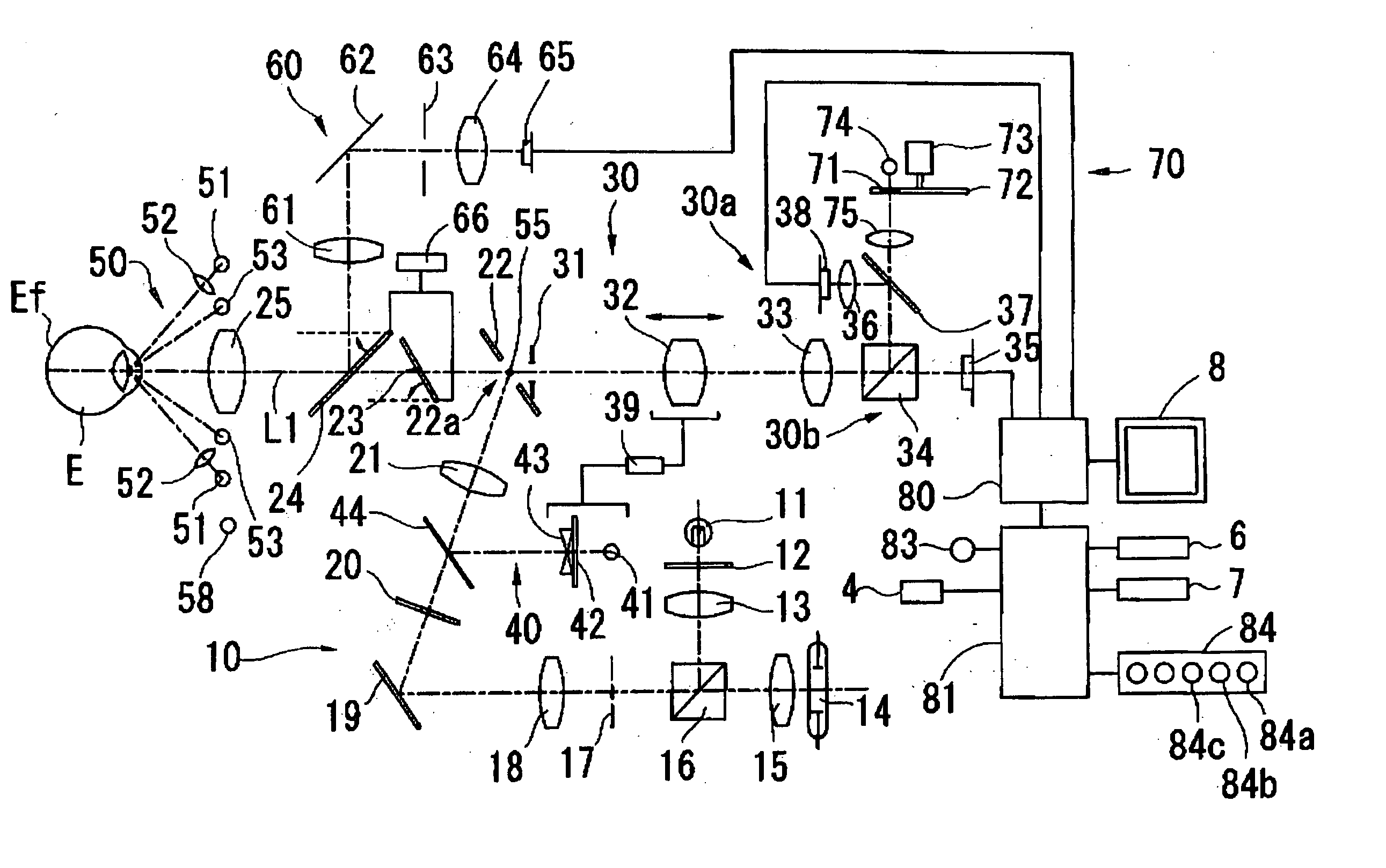
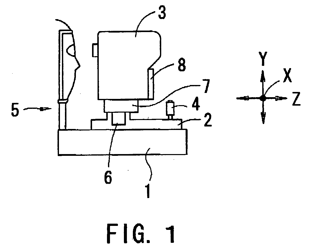
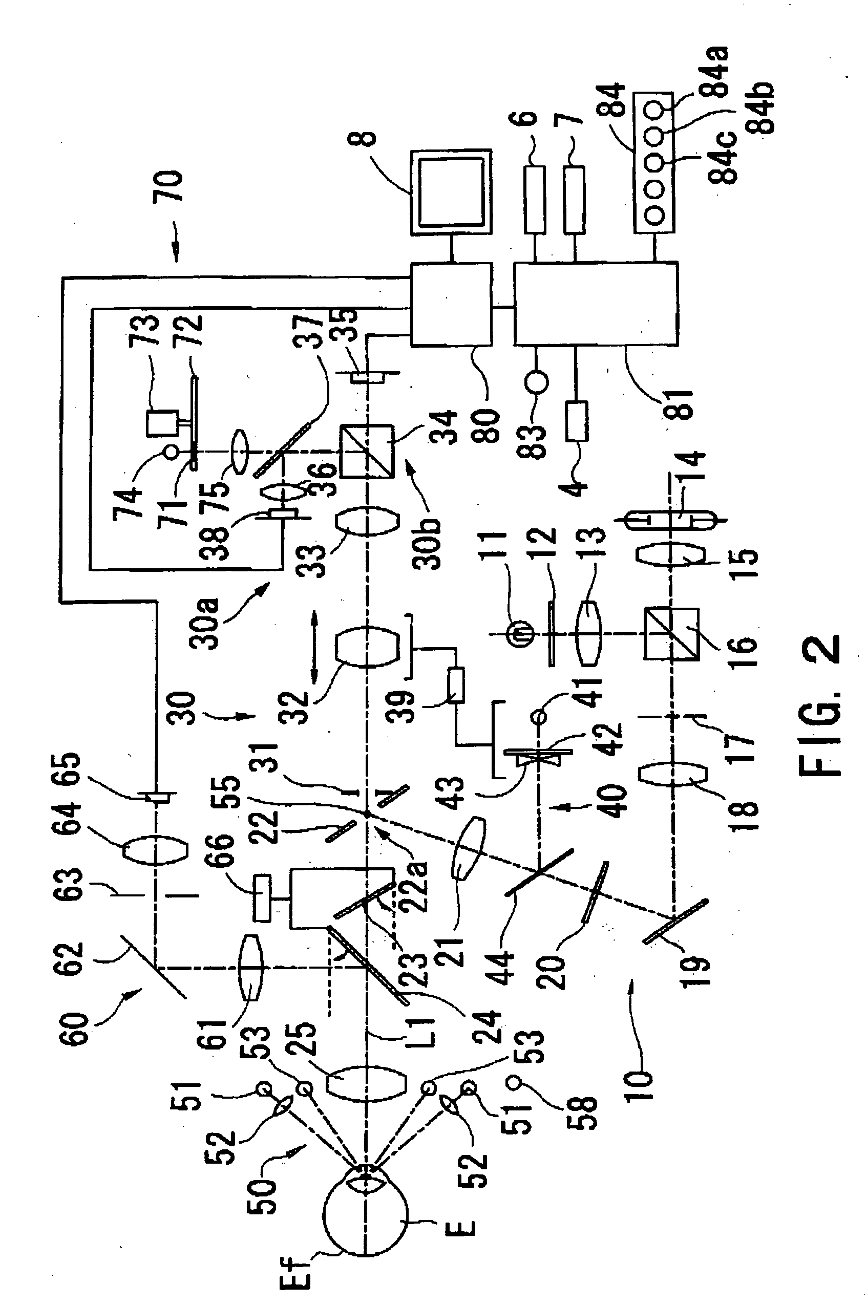
[0022] A detailed description of one preferred embodiment of a fundus camera embodied by the present invention is provided below with reference to the accompanying drawings. FIG. 1 is a view showing a schematic configuration of a fundus camera of non-mydriasis type consistent with the preferred embodiment of the present invention.

[0023] The fundus camera is provided with a base 1, a mobile base 2 movable in a right / left direction (hereinafter referred to as an “X-direction”) and a back / forth direction (hereinafter referred to as a “Z-direction”) with reference to the base 1 through tilting operation of a joystick 4, a photographing part 3 movable in the right / left direction, an up / down direction (hereinafter referred to as a “Y-direction”), and the back / forth direction with reference to the mobile base 2 under control of a control part 81 described later, and a face support part 5 fixedly arranged on the base 1 for supporting a face (a head) of an examinee. A Z table movable in the...


PUM


Abstract

A fundus camera capable of performing alignment easily and efficiently, and photographing a fundus favorably. A fundus camera for photographing a fundus of an eye of an examinee has a photographing part in which a fundus photographing optical system is arranged, a fundus observation optical system having a first image-pickup element which picks up an image of the fundus, an anterior-segment observation optical system having a second image-pickup element which picks up an image of an anterior-segment of the eye, a display unit capable of displaying the image of the fundus picked up by the first image-pickup element and the image of the anterior-segment picked up by the second image-pickup element, and a control part which obtains information on alignment of the photographing part with the eye and decides which of the image of the fundus and the image of the anterior-segment is to be displayed on the display unit.

Description

BACKGROUND OF THE INVENTION [0001] 1. Field of the Invention [0002] The present invention relates to a fundus camera for photographing a fundus of an eye of an examinee. [0003] 2. Description of Related Art [0004] Conventionally, there is known a fundus camera where rough alignment of a photographing part with an eye of the examinee is firstly performed while an image of an anterior-segment of the eye displayed on a monitor is observed, and then fine alignment with a fundus portion to be photographed is performed while an image of a fundus of the eye displayed on the monitor through display switching is observed. [0005] Further, there is known a fundus camera which projects target light for working distance detection onto a cornea of an eye of an examinee, and fine alignment is performed while a corneal reflex of the target light (a working dot) is observed along with an image of a fundus of the eye. [0006] However, rich experience is required to make proper display switching betwee...

Claims


Application Information

Patent Timeline
Patent Type & Authority Applications(United States)
IPC IPC(8): A61B3/14A61B3/12A61B3/15
CPCA61B3/0058A61B3/152A61B3/145A61B3/12
Inventor ICHIKAWA, NAOKI
Owner NIDEK CO LTD
Why Eureka
Try Eureka