
Image processing apparatus, image processing program, electronic camera, and image processing method for smoothing image of mixedly arranged color components

Inactive Publication Date: 2006-06-08
NIKON CORP
View PDF13 Cites 13 Cited by
  • Summary
  • Abstract
  • Description
  • Claims
  • Application Information

AI Technical Summary

Benefits of technology

[0015] In view of solving the foregoing problems, it is an object of the present invention to easily, efficiently perform sophisticated spatial filtering conforming to image structures.
[0016] Another object of the present invention is to provide an image processing technique for realizing appropriate noise removal while maintaining resolution and contrast regardless of changes in the imaging sensitivity.

Problems solved by technology

However, this processing has had a problem in complicating the image processing since the color interpolation, the color system conversion processing, and the spatial filtering must be performed separately.
There have thus been problems such as extended processing time for the RAW data.
The complexity of the image processing has also produced another problem that image processing ICs to be mounted on the electronic cameras are to be complex in configuration.
Furthermore, these processings (the color interpolation, the color system conversion processing, and the spatial filtering) are applied to a single image step by step, which causes another problem that minute image information can be lost easily in the course of the cumulative processes.
It is also disadvantageous that minute image information can be lost easily.
This change in the imaging sensitivity causes large variations in the noise amplitude of the captured images.
Therefore, over-blurring may occur for low sensitivity images with high S / N due to excessive smoothing by the conversion filter, whereas color artifacts may be closed up or granularity may be left for high sensitivity images with low S / N due to inadequate smoothing by the conversion filter.

Method used


Image

  • Image processing apparatus, image processing program, electronic camera, and image processing method for smoothing image of mixedly arranged color components
  • Image processing apparatus, image processing program, electronic camera, and image processing method for smoothing image of mixedly arranged color components
  • Image processing apparatus, image processing program, electronic camera, and image processing method for smoothing image of mixedly arranged color components

Examples


first embodiment

Effects and Others of First Embodiment

[0156] As has been described, according to the first embodiment, the groups of coefficient tables having different spatial frequency characteristics are prepared in advance, and the groups of coefficient tables are switched for use in accordance with the analysis of the image structure (steps S43 and S48). As a result, the basically-separated image processes of color system conversion and spatial filtering in consideration of the image structure can be performed by a single weighted addition.

[0157] This eliminates the need to perform the spatial filtering and the color system conversion separately, thereby allowing a significant reduction in time necessary for processing the RAW data.

[0158] Besides, since what is necessary is a single weighted addition, it is also possible to reduce deterioration of image information as compared to the background art where color system conversion and spatial filtering are conducted step by step.

[0159] Moreove...

second embodiment

[0164] The electronic camera (including an image processing apparatus) according to a second embodiment performs color interpolation on RGB Bayer-array RAW data (corresponding to the first image), thereby generating image data that has RGB signal components arranged entirely on each pixel (corresponding to the second image).

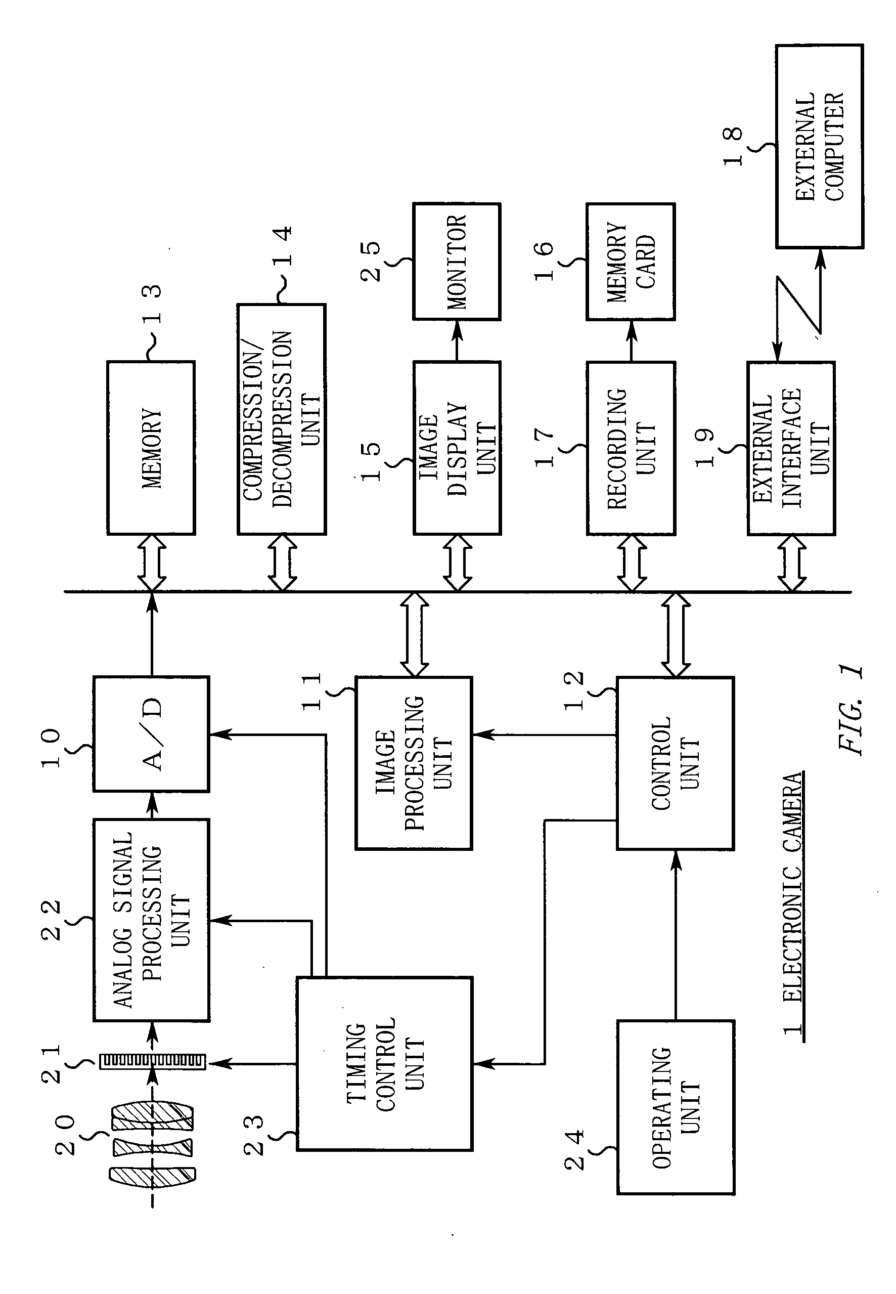
[0165] The configuration of the electronic camera (FIG. 1) is the same as in the first embodiment. Description thereof will thus be omitted.

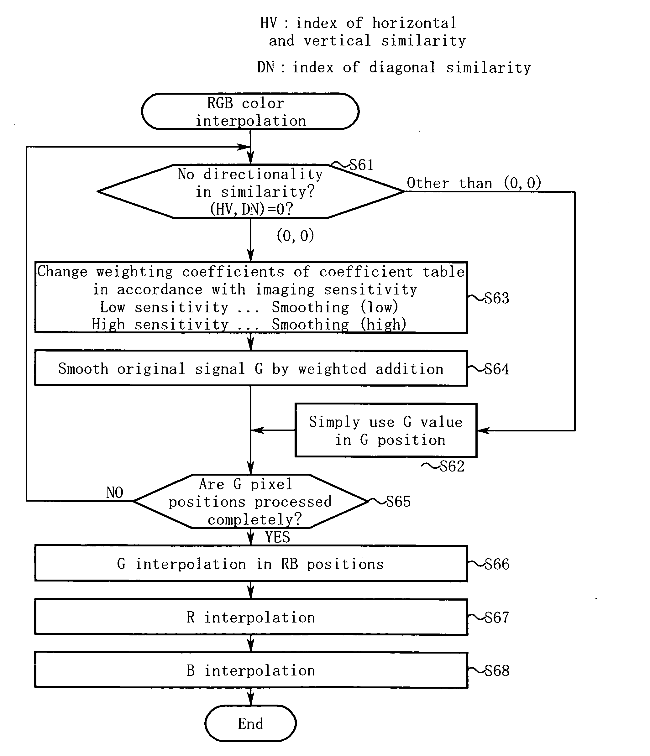
[0166]FIG. 14 is a flowchart for explaining the color interpolation according to the second embodiment. Hereinafter, the operation of the second embodiment will be described along the step numbers shown in FIG. 14.

[0167] Step S61: The image processing unit 11 makes a similarity judgment on a G pixel [i,j] of RAW data to be processed, thereby determining whether or not the location has similarities indistinguishable in any direction, i.e., whether or not the location has high isotropy, having no significant directionality i...

third embodiment

[0189] The electronic camera (including an image processing apparatus) according to a third embodiment performs color interpolation on RGB Bayer-array RAW data (corresponding to the first image), thereby generating image data that has RGB signal components arranged on each pixel (corresponding to the second image).

[0190] The configuration of the electronic camera (FIG. 1) is the same as in the first embodiment. Description thereof will thus be omitted.

[0191]FIG. 17 is a flowchart for explaining color interpolation according to the third embodiment. Hereinafter, the operation of the third embodiment will be described along the step numbers shown in FIG. 17. Step S71: The image processing unit 11 makes a similarity judgment on a G pixel [i,j] of RAW data to be processed, thereby determining whether or not the similarities in all the directions are higher than predetermined levels, i.e., whether or not the location has a high flatness without any significant directionality in its ima...


PUM


Abstract

An image processing apparatus converts a first image composed of one of first to nth color components (n≧2) arranged on each pixel, into a second image composed of all the first to nth components arranged entirely on each pixel. A smoothing unit of this image processing apparatus applies smoothing to a pixel position of the first color component in the first image, using the first color component of the surrounding pixels, and outputs the first color component having been smoothed as the first color component in the pixel position of the second image. This smoothing unit further includes a control unit that changes the characteristic of a smoothing filter in accordance with an imaging sensitivity at which the first image is captured.

Description

CROSS REFERENCE TO RELATED APPLICATION [0001] This application is a continuation application of International Application PCT / JP 2004 / 009601, filed Jun. 30, 2004, designating the U.S., and claims the benefit of priority from Japanese Patent Application No. 2003-186629, filed on Jun. 30, 2003, the entire contents of which are incorporated herein by reference.BACKGROUND OF THE INVENTION [0002] 1. Field of the Invention [0003] The present invention relates to an image processing technique for converting a first image (for example, RAW data) having color components arranged mixedly, to generate a second image having at least one kind of components arranged on each pixel. [0004] 2. Description of the Related Art (Prior Art 1) [0005] Conventionally, there have been known electronic cameras that perform spatial filtering such as edge enhancement and noise removal. [0006] Spatial filtering of this type is typically applied to luminance and chrominance planes YCbCr (the luminance component ...

Claims


Application Information

Patent Timeline
IPC IPC(8): H04N1/409H04N9/04
CPCG06T3/4015H04N5/243H04N9/045H04N2209/046H04N23/76H04N23/843H04N25/134
Inventor CHEN, ZHEHONGISHIGA, KENICHI
Owner NIKON CORP
Learn More