
Reinforced self-standing earth retaining structure using an arching effect and an underground excavation construction method using the same

a self-standing earth retaining structure and arching effect technology, applied in excavations, artificial islands, constructions, etc., can solve the problems unable to support a horizontal force with only a vertical member and not a horizontal member in view of structural mechanics, and unable to achieve the effect of reducing the work space for entering equipmen

Inactive Publication Date: 2012-03-29
PARK GANG HO +1
View PDF8 Cites 14 Cited by
  • Summary
  • Abstract
  • Description
  • Claims
  • Application Information

AI Technical Summary

Benefits of technology

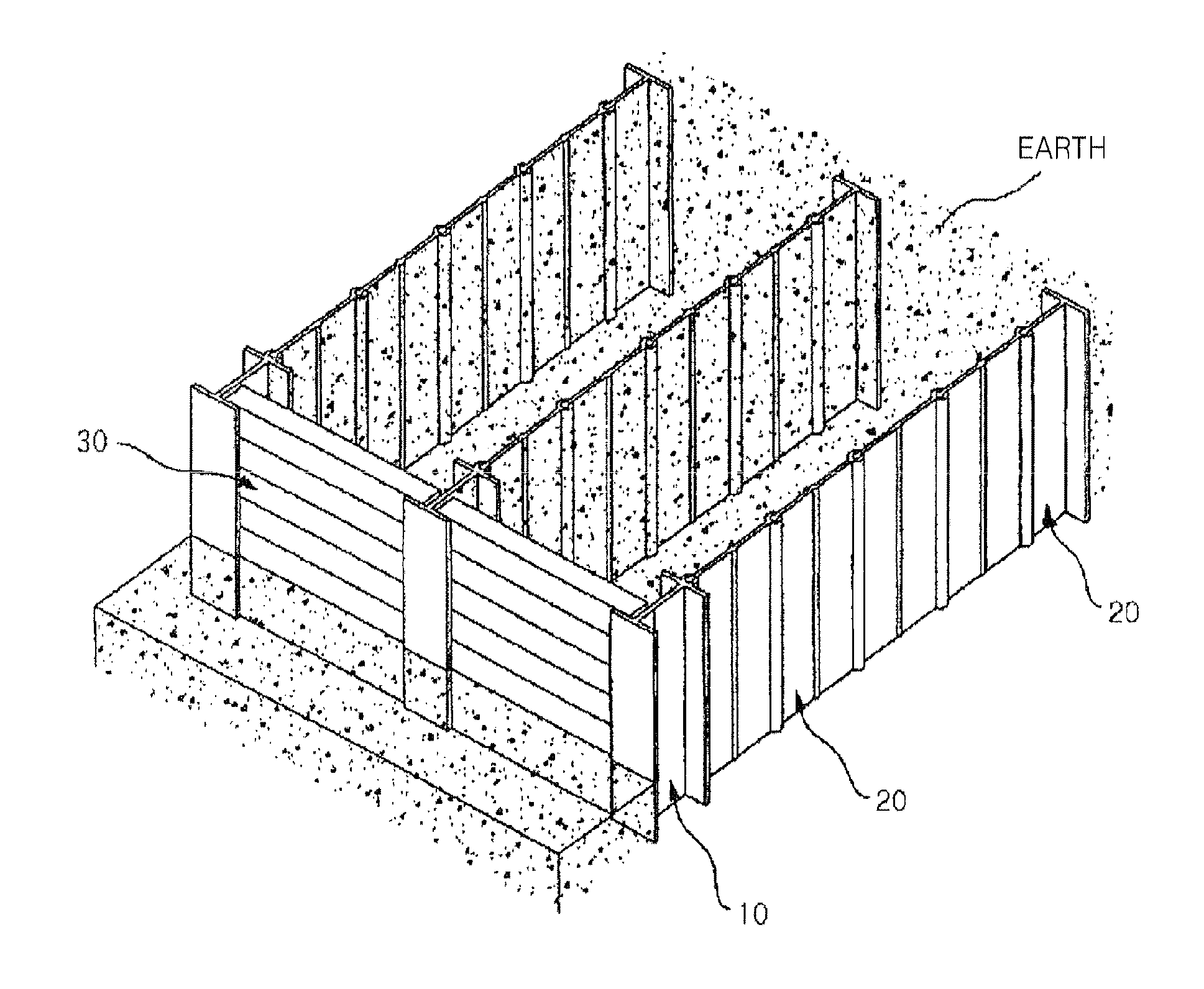
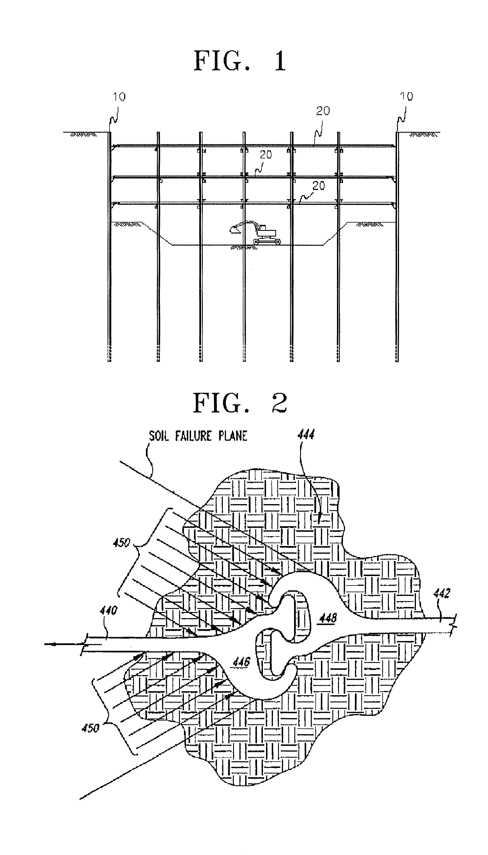
[0030]The present invention provides a reinforced self-standing earth retaining structure, which uses an arching effect, which is located at the back side of an excavation space so as not to be an obstacle to an excavation work so that a large excavation space may be used. Accordingly, an excavation work in a limited space in a downtown area where tall buildings are densely located may be easily and efficiently performed.
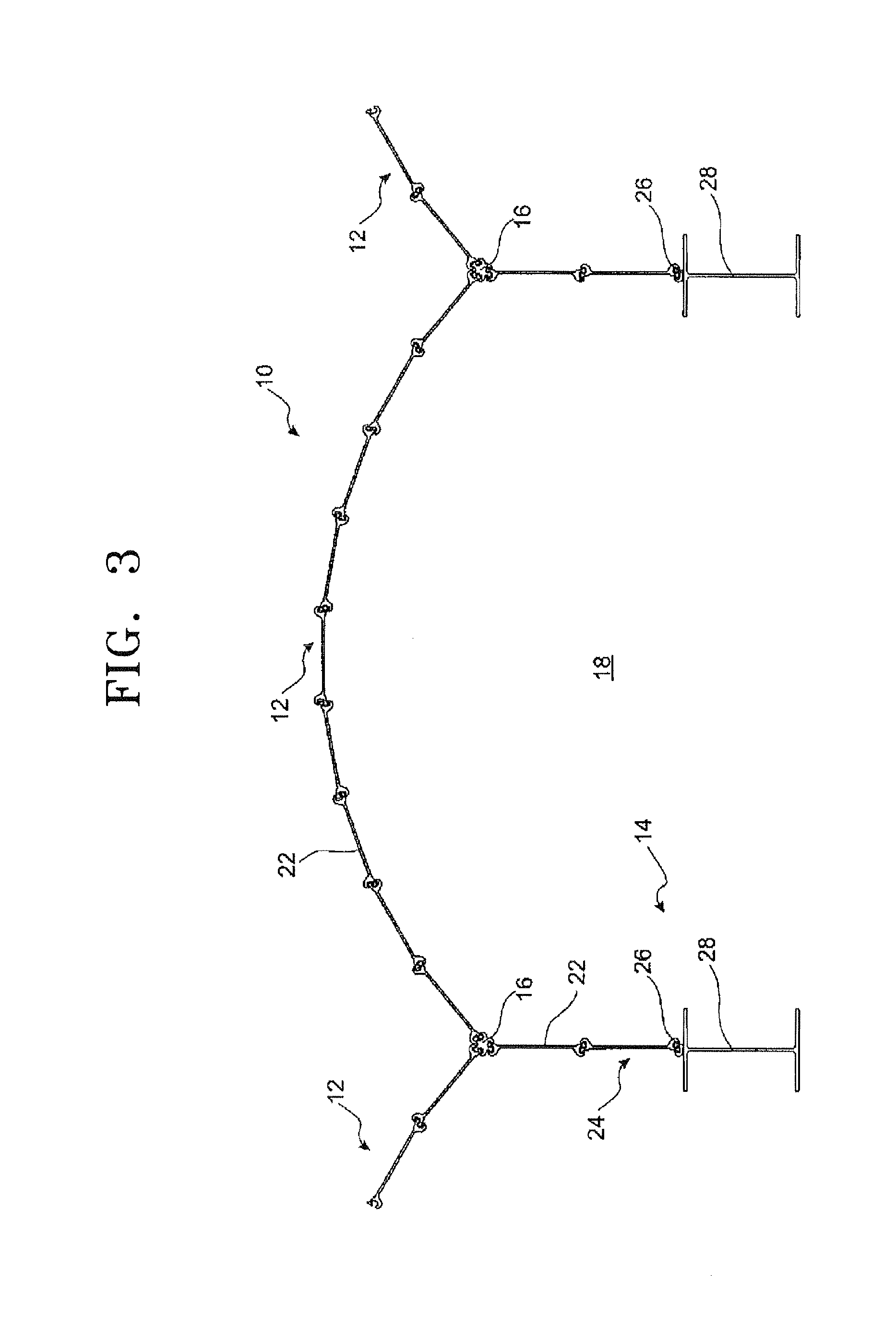
[0031]The present invention provides a reinforced self-standing earth retaining structure which may increase the rigidity of a connection portion of a group of serial sheet panels using upper and lower fixing devices by making the connection portion of the sheet panel be a combined section, and simultaneously facilitate the assembly and disassembly of the connection portion of the sheet panel due to a simple structure of the upper and lower fixing devices and thus make collection of installed sheet panels easy after construction is completed.

Problems solved by technology

Supporting a horizontal force with only a vertical member and not a horizontal member is impossible in view of structural mechanics.
The struts in the latitudinal and longitudinal directions are obstacles that decrease a work space for entering equipment for an excavation work and discharging soil to the outside.
However, the removal of the struts from the level B1 is prevented by the struts in the latitudinal and longitudinal directions so that the excavation work is hindered.
Such problems also affect the construction of the levels B2, B3, B4, etc.
Thus, the strut construction method is problematic because the struts installed within an excavation space facing the soldier pile which narrows a work space for an excavation work and a soil discharge work.
Korean Patent Publication No. 2008-45182 points out that U.S. Pat. No. 6,715,964 B2 has a problem in that a connection portion for coupling a sheet-pile wall sectioning portion to an anchorage receives a very high tension force due to an earth pressure of ground retaining from a surrounding area.

Method used


Image

  • Reinforced self-standing earth retaining structure using an arching effect and an underground excavation construction method using the same
  • Reinforced self-standing earth retaining structure using an arching effect and an underground excavation construction method using the same
  • Reinforced self-standing earth retaining structure using an arching effect and an underground excavation construction method using the same

Examples


Embodiment Construction

[0066]The attached drawings for illustrating exemplary embodiments of the present invention are referred to in order to gain a sufficient understanding of the present invention, the merits thereof, and the objectives accomplished by the implementation of the present invention. Hereinafter, the present invention will be described in detail by explaining exemplary embodiments of the invention with reference to the attached drawings. Like reference numerals in the drawings denote like elements.

[0067]Since the present invention relates to a reinforced self-standing earth retaining structure using an arching effect, a general outline of an arching effect will be first described and then the arching effect in view of geotechnical engineering will be described.

[0068]A) General Outline of Arching Effect

[0069]A general outline of an arching effect will be described below with reference to FIGS. 5A and 5B.

[0070]When sand is contained in a box with an open upper cover plate and a hole of a dia...


PUM


Abstract

In a reinforced self-standing earth retaining structure using an arching effect, a soldier pile integrally formed with a soldier pile insertion portion in a vertical direction in a flange at one end of the soldier pile in which a lagging is inserted is installed at a width B to be perpendicular to the ground. A sheet panel protruding portion is inserted in and connected to the soldier pile insertion portion. A sheet panel protruding portion is serially inserted in a sheet panel insertion portion. A compression support plate protruding portion is inserted in and coupled to the sheet panel insertion portion. A relationship between a length L of a group of serial sheet panels and the width B between two groups of serial sheet panels is 0.5≦L / B≦3.0 in a range of an internal friction angle of earth φ=10˜34° and a range of an adhesive power C=0.0˜5.0 ton / m2 so that a back earth pressure is not applied to the front lagging due to the arching effect.

Description

CROSS-REFERENCE TO RELATED PATENT APPLICATIONS[0001]This application claims the benefit of a PCT International Application No. PCT / KR / 2010 / 008812, filed on Dec. 9, 2010, the disclosure of which is incorporated herein in its entirety by reference.BACKGROUND OF THE INVENTION[0002]1. Field of the Invention[0003]The present invention relates to a reinforced self-standing earth retaining structure using an arching effect and an underground excavation construction method using the same, and more particularly, to a reinforced self-standing earth retaining structure, which uses an arching effect, that supports a back earth pressure generated by vertical excavation.[0004]2. Description of the Related Art[0005]A reinforced self-standing earth retaining structure, which uses an arching effect, that is installed in the rear of an excavation space does not interfere with an excavation work and helps an efficient excavation work. In particular, since a back earth pressure is not applied to a lagg...

Claims


Application Information

Patent Timeline
Patent Type & Authority Applications(United States)
IPC IPC(8): E02D29/02
CPCE02D5/02E02D17/04E02D5/04
Inventor PARK, GANG HOKIM, JUN
Owner PARK GANG HO
Learn More