Plate fin heat exchanger and repair method for plate fin heat exchanger

a heat exchanger and plate fin technology, applied in the field of plate fin heat exchangers, can solve the problems of serious production loss and considerable working time, and achieve the effects of short service life, sufficient pressure resistance performance, and smooth fluid distribution

Inactive Publication Date: 2014-02-27
KOBE STEEL LTD
View PDF5 Cites 9 Cited by
  • Summary
  • Abstract
  • Description
  • Claims
  • Application Information

AI Technical Summary

Benefits of technology

[0013]The present invention is achieved in order to solve the problems described above, and an object thereof is to, even in a case where a partition wall partitioning an outermost-layer flow passage of a heat exchange unit and an internal space of a protection unit adjacent to the flow passage is damaged and a fluid flows out from a release portion provided in the protection unit to an exterior, restore a heat exchanger into a state that no fluid flows out to the exterior and the heat exchanger has a sufficient pressure resistance performance for a short time.
[0015]In this plate fin heat exchanger, the protection unit fin plate of the protection unit has such strength that the coupling state between the outer surface of the outermost partition wall which is in contact with the protection unit fin plate and the inner surface of the protection unit main body facing the outer surface (bonding plate to be described later) is maintained even in a case where the inner pressure set as the design pressure for the part of the heat exchange unit constituting the outermost-layer flow passage adjacent to the protection unit is applied to the internal space of the protection unit. Thus, even when the inner pressure corresponding to the design pressure is applied to the internal space of the protection unit, the strength resistant against the inner pressure can be given to the protection unit. Therefore, even when the fluid flowing through the outermost-layer flow passage of the heat exchange unit flows into the internal space of the protection unit, the protection unit can be resistant against pressure of the fluid. As a result, the internal space of the protection unit can be used as part of the outermost-layer flow passage of the heat exchange unit adjacent to the protection unit. Therefore, in a case where the heat exchanger is continuously used even after the outermost partition wall is damaged in the heat exchanger and the fluid flows into the internal space of the protection unit from the outermost-layer flow passage, only by bringing the release portion of the protection unit into a sealed state, the heat exchanger can be brought into a state that the heat exchanger has a sufficient pressure resistance performance while preventing the fluid from flowing out from the heat exchanger to the exterior. That is, the protection unit can be utilized as the heat exchange unit. Therefore, in this heat exchanger, the heat exchanger can be restored into a state that no fluid flows out to the exterior and the heat exchanger has a sufficient pressure resistance performance for a short time in comparison to the conventional plate fin heat exchanger requiring repair tasks of detaching the header for supplying the fluid by cutting the welded part, sealing the inlet of the outermost-layer flow passage, and welding the header for supplying the fluid again.
[0021]With this configuration, since the release port is sealed by the sealing material in a state that the fluid does not flow into the internal space of the protection unit main body, foreign substances, rainwater, and the like can be prevented from invading the internal space of the protection unit main body through the release port. In addition, in a case where the fluid flows into the internal space of the protection unit main body from the outermost-layer flow passage and the inner pressure of the internal space of the protection unit main body is increased, the release port can be opened so as to release the fluid from the internal space to the exterior.
[0024]With this repair method for the plate fin heat exchanger, even in a case where the outermost partition wall is damaged and the fluid flows into the internal space of the protection unit from the outermost-layer flow passage of the heat exchange unit, only by performing the sealing step of bringing the release portion into a sealed state, the heat exchanger can be repaired into a state that no fluid flows out to the exterior and the heat exchanger has a sufficient pressure resistance performance. Therefore, the heat exchanger can be repaired into a continuously usable state for a short time.
[0026]With this configuration, in a case where the outermost partition wall is damaged, and the internal space of the protection unit is to be used as part of the outermost-layer flow passage of the heat exchange unit, the opening can be formed on the outermost partition wall so as to smoothen fluid distribution between the outermost-layer flow passage and the internal space of the protection unit.
[0027]As described above, according to the present invention, even in a case where the partition wall partitioning the outermost-layer flow passage of the heat exchange unit and the internal space of the protection unit adjacent to the flow passage is damaged and the fluid flows out from the release portion provided in the protection unit to the exterior, the heat exchanger can be restored into a state that no fluid flows out to the exterior and the heat exchanger has a sufficient pressure resistance performance for a short time.

Problems solved by technology

However, such repair requires a considerably long working time.
Thus, a stop period of the plant or the like where the heat exchanger is used is increased, so that a production loss becomes serious.

Method used


Image

  • Plate fin heat exchanger and repair method for plate fin heat exchanger
  • Plate fin heat exchanger and repair method for plate fin heat exchanger
  • Plate fin heat exchanger and repair method for plate fin heat exchanger

Examples


Embodiment Construction

[0044]Hereinafter, an embodiment of the present invention will be described with reference to the drawings.

[0045]Firstly, with reference to FIGS. 1 to 10, a configuration of a plate fin heat exchanger according to one embodiment of the present invention will be described.

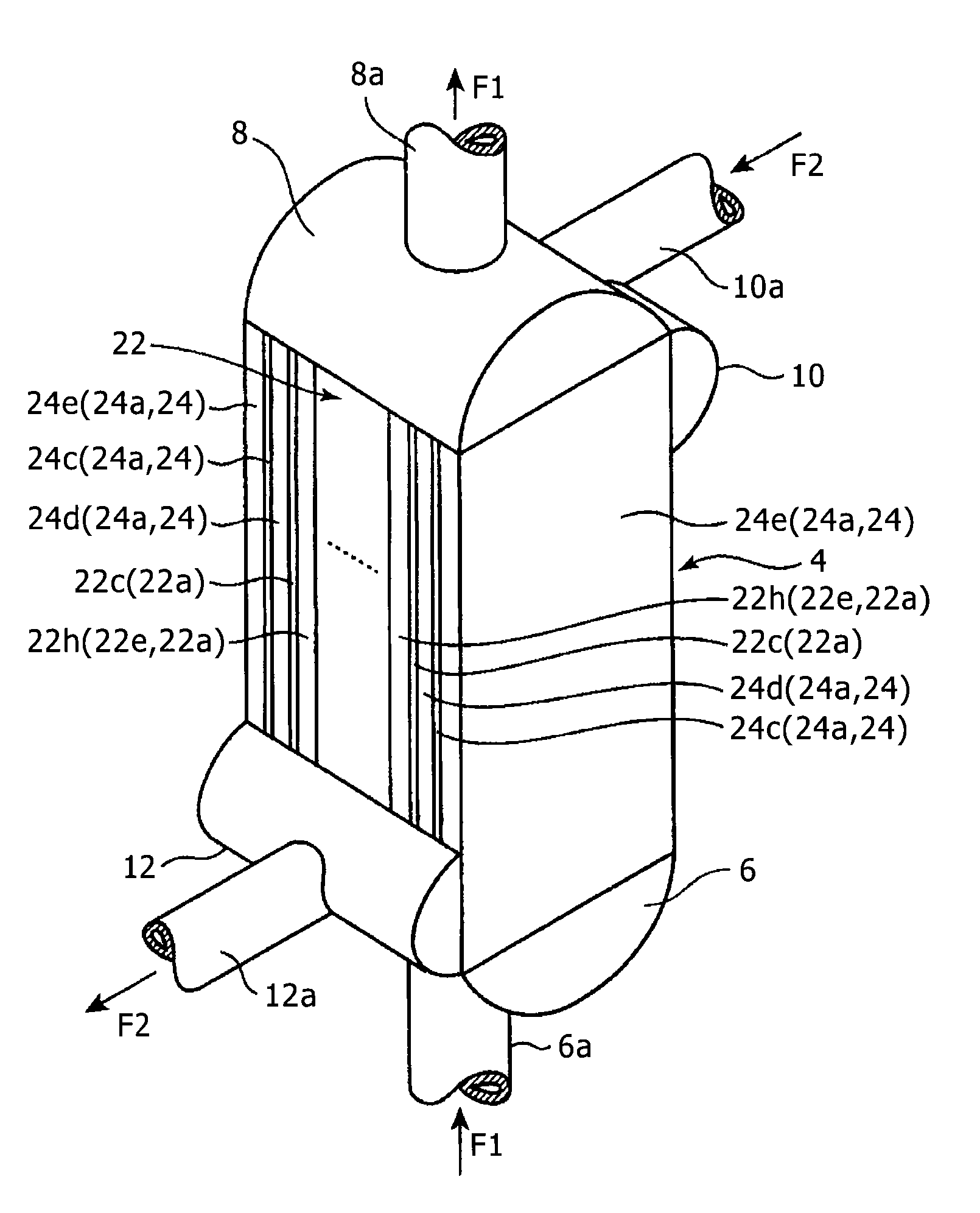
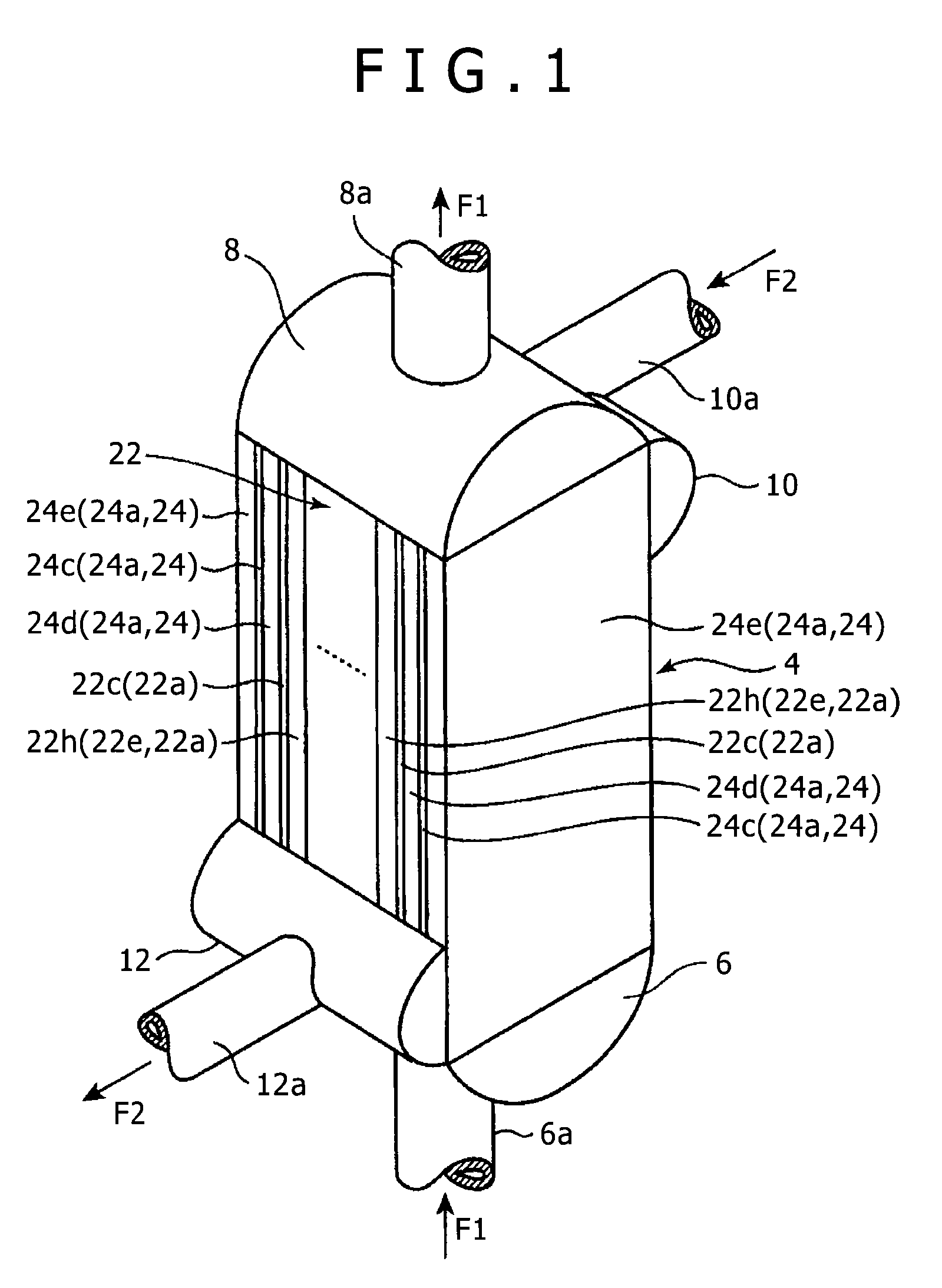
[0046]A plate fin heat exchanger 1 according to the present embodiment (hereinafter, also simply referred to as the “heat exchanger 1”) is a heat exchanger in which heat exchange is performed between a plurality of fluids flowing inside. Specifically, as shown in FIGS. 1 to 3, the plate fin heat exchanger 1 is provided with a heat exchanger main body 4, a first supply header 6, a first collection header 8, a second supply header 10, and a second collection header 12.

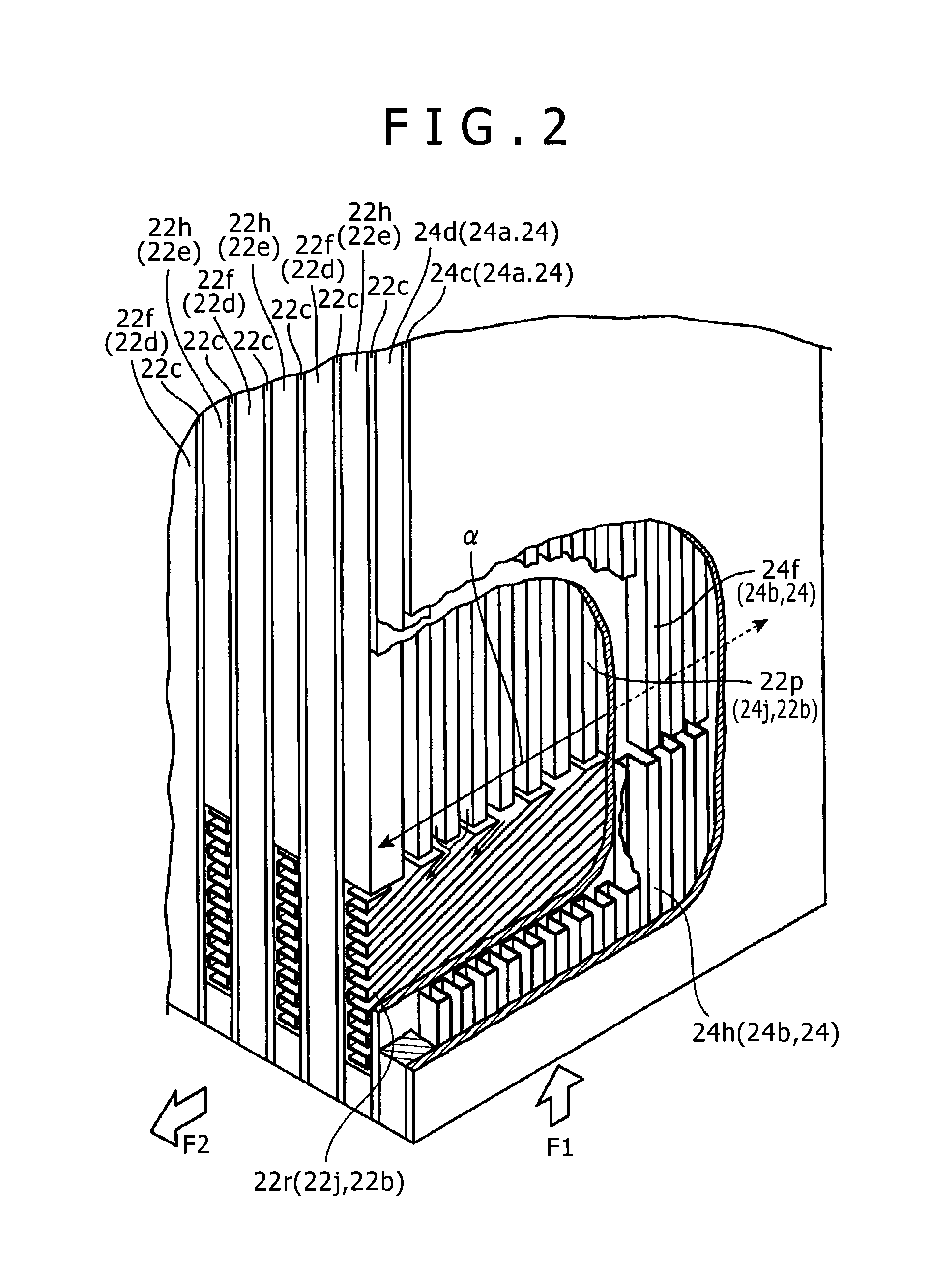
[0047]The heat exchanger main body 4 is formed by a heat exchange unit 22 and two protection units 24. In the present embodiment, a material of the heat exchange unit 22 and the protection units 24 is an aluminum alloy.

[0048]The heat exchange unit 22 is ...


PUM

PropertyMeasurementUnit
timeaaaaaaaaaa
thicknessaaaaaaaaaa
thicknessaaaaaaaaaa

Abstract

In a heat exchanger of the present invention, a release port for, in a case where a fluid flows into an internal space, releasing the fluid to an exterior is provided in a protection unit main body of each of protection units arranged on both outer sides of a heat exchange unit, and a protection unit fin plate of the protection unit has such strength that a coupling state between an outer surface of an outermost-layer partition plate and a bonding plate of the protection unit main body facing the outer surface is maintained even in a case where an inner pressure set as a design pressure for a part of the heat exchange unit constituting an outermost-layer flow passage adjacent to the protection unit is applied to the internal space of the protection unit main body of the protection unit.

Description

BACKGROUND OF THE INVENTION[0001]1. Field of the Invention[0002]The present invention relates to a so-called plate fin heat exchanger in which a fin plate is installed, and a repair method for the same.[0003]2. Description of the Related Art[0004]Conventionally, there is a known plate fin heat exchanger (hereinafter, also simply referred to as the “heat exchanger”) described in Japanese Unexamined Patent Application Publication No. H7-167580. This heat exchanger is provided with a heat exchange unit in which a number of flow passages are aligned in laminated blocks called a core. Specifically, as shown in FIGS. 15 and 16, a heat exchange unit 100 is provided with a plurality of flat plate shape tube plates 102 arranged in parallel at intervals, a corrugated plate shape fin plate 104 arranged between the tube plates 102, and side bars 106 respectively arranged on both sides of the fin plate 104 so as to sandwich this fin plate 104 from both sides in the width direction. The side bars...

Claims


Application Information

Patent Timeline
Patent Type & Authority Applications(United States)
IPC IPC(8): F28F3/02B23P15/26
CPCB23P15/26F28F3/02F28F2265/16F28F11/00F28F27/00F28D9/0062F28F3/025Y10T29/49352
Inventor MITSUHASHI, KENICHIRO
Owner KOBE STEEL LTD
Why Eureka
Try Eureka