
Internally grooved heat transfer tube for high-pressure refrigerant

a heat transfer tube and heat exchanger technology, applied in indirect heat exchangers, refrigeration components, lighting and heating apparatus, etc., can solve the problems of poor heat transfer performance, deterioration of the workability of the tube, poor bonding of the tube, etc., to achieve the effect of improving heat transfer performance and strengthening pressure resistan

Inactive Publication Date: 2007-08-30
SUMITOMO LIGHT METAL INDS LTD
View PDF6 Cites 10 Cited by
  • Summary
  • Abstract
  • Description
  • Claims
  • Application Information

AI Technical Summary

Benefits of technology

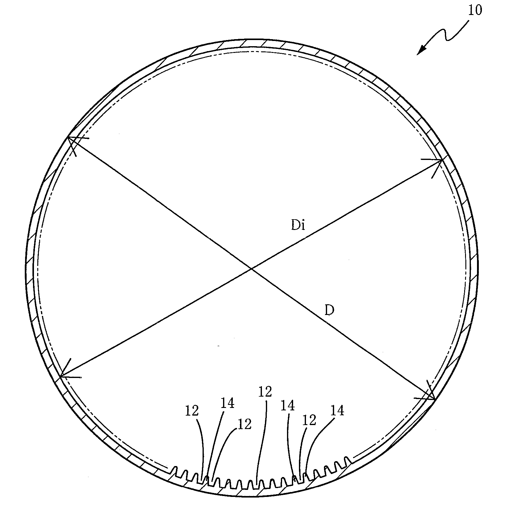
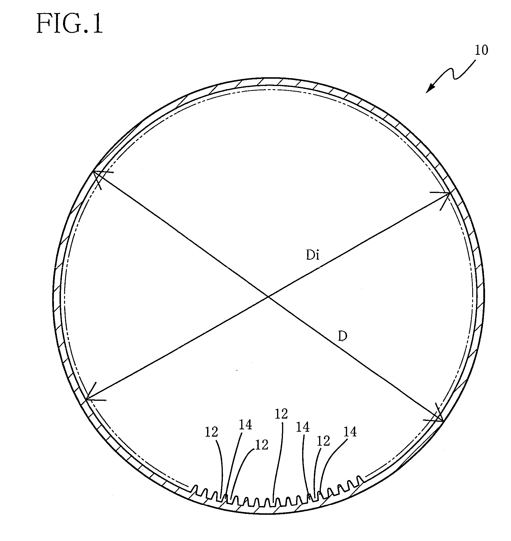
[0027] In the internally grooved heat transfer tube for a high-pressure refrigerant according to the present invention, the strength for pressure resistance and the heat transfer performance can be improved at one time. Accordingly, the high-pressure refrigerant whose typical example is a carbon dioxide gas can be advantageously used in a cross fin tube type heat exchanger formed by using the internally grooved heat transfer tube constructed as described above.

Problems solved by technology

However, as the global environmental problems become serious in these years, CFC and HCFC refrigerants containing chlorine are being replaced with HFC refrigerants from the standpoint of prevention of destruction of the ozone layer.
However, the change in the material for the heat transfer tube to stainless or aluminum undesirably may result in deteriorated workability of the tube or poor bonding of the tube.
The disclosed heat transfer tube, however, has a smooth inner surface and accordingly its heat transfer performance is insufficient as compared with the internally grooved heat transfer tube.
Therefore, it is technically difficult to fix the heat transfer tube with the diameter of 6 mm or smaller to the heat-dissipating fins by the mechanical tube-expanding method.
Accordingly, it is rather difficult to employ the mechanical tube-expanding method unless the heat transfer tube with a relatively large diameter is used.
This hydraulic tube-expanding method requires a complicated arrangement and is inferior in view of mass production.
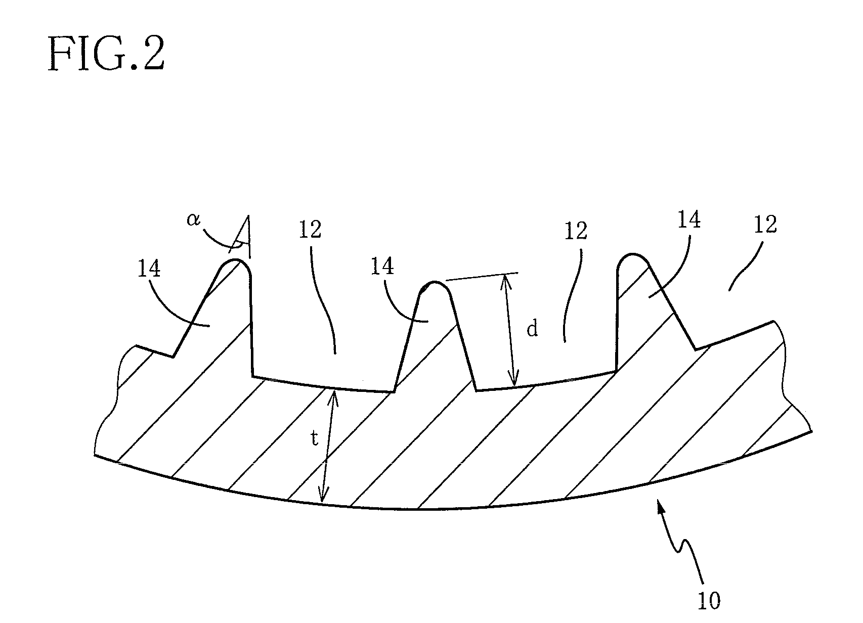
Further, in the current technique of manufacturing the internally grooved heat transfer tube, since the groove depth tends to be decreased with an increase in the groove bottom thickness, it is difficult to improve the heat transfer performance of the internally grooved heat transfer tube by employing techniques for attaining high performance such as an increase in the height of the internal fins and a decrease in the width of the internal fins.
In addition, in the case where the groove bottom thickness is increased, a large force acts on the tube when the tube is expanded by the mechanical tube-expanding method, causing a problem that the fins are collapsed due to the pressure upon the mechanical tube expanding if the fins each formed between adjacent two grooves on the inner surface of the tube are configured to have an increased height or an increased width.
Further, it is not desirable to change the material for the heat transfer tube and reduce the outside diameter of the tube in an attempt to improve the strength for pressure resistance since the change in the material and the reduction in the tube diameter lead to deteriorated workability.
Moreover, where the strength for pressure resistance is enhanced simply by increasing the groove bottom thickness, the groove depth is reduced due to limitation in working under the present circumstances.

Method used


Image

  • Internally grooved heat transfer tube for high-pressure refrigerant
  • Internally grooved heat transfer tube for high-pressure refrigerant
  • Internally grooved heat transfer tube for high-pressure refrigerant

Examples


embodiment

[0048] The characteristic of the present invention will be further clarified by indicating an embodiment of the invention. It is to be understood that the invention is not limited to the description of the embodiment.

[0049] Initially, as test heat transfer tubes, there are prepared internally grooved heat transfer tubes according to Examples 1-6 having mutually different specifications shown in the following TABLE 1. In each of those test heat transfer tubes, a multiplicity of internal grooves are formed as spiral grooves on the inner surface of the tube so as to extend with a prescribed inclination angle (lead angle) with respect of the tube axis. Further, the outside diameter, the groove bottom thickness, the groove depth, the cross sectional area of each groove, and the number of grooves are determined so as to satisfy the relational expressions according to the present invention. For comparison, there is prepared, as a Comparative example 1, a tube having ordinary specification...


PUM

PropertyMeasurementUnit
Thicknessaaaaaaaaaa
Pressureaaaaaaaaaa
Diameteraaaaaaaaaa

Abstract

An internally grooved heat transfer tube for a cross fin tube type heat exchanger of a refrigerating air-conditioning water supply apparatus using a high-pressure refrigerant, wherein an intra-tubular heat transfer rate is improved while maintaining a sufficient strength for pressure resistance. A heat transfer tube formed of copper or copper alloy has internal fins between internal grooves. In the tube, t / D is not smaller than 0.041 and not greater than 0.146, d2 / A is not smaller than 0.75 and not greater than 1.5, where D [mm] is an outside diameter of the tube, t [mm] is a groove bottom thickness, d [mm] is a depth of each groove, and A [mm2] is a cross sectional area of each groove. N / Di is not smaller than 8 and not greater than 24 where N is a number of grooves, and Di is a maximum inside diameter corresponding to an inside diameter of the tube.

Description

[0001] This application is a continuation of the International Application No. PCT / JP2005 / 021672 filed Nov. 25, 2005, which claims the benefit under 35 U.S.C. § 119(a)-(d) of Japanese Patent Application 2004-350357, filed Dec. 2, 2004, the entireties of which are incorporated herein by reference.TECHNICAL FIELD [0002] The present invention relates to an internally grooved heat transfer tube for a heat exchanger used in various types of refrigerating air-conditioning water heater apparatus. More particularly, the invention relates to such an internally grooved heat transfer tube for a cross fin tube type heat exchanger using a high-pressure refrigerant whose typical example is a carbon dioxide gas. BACKGROUND ART [0003] Conventionally, a heat exchanger which works as an evaporator or a condenser is employed in air-conditioning equipment such as a home air conditioner, a vehicle air conditioner or a package air conditioner, a refrigerator or the like. In the home air conditioner for i...

Claims


Application Information

Patent Timeline
IPC IPC(8): F28F13/18
CPCF25B39/00F28F1/40F25B2309/061
Inventor SASAKI, NAOEKONDO, TAKASHIKAKIYAMA, SHIRO
Owner SUMITOMO LIGHT METAL INDS LTD
Learn More