Image sensor unit and image taking apparatus

a technology of image sensor and image, which is applied in the field of image sensor unit and image taking apparatus, can solve the problems of insufficient sensitivity, large image taking apparatus or cost increase, and difficulty in compensating such a large brightness variation, and achieve excellent photographing through day and night

Inactive Publication Date: 2009-09-08
FUJIFILM CORP
View PDF8 Cites 11 Cited by
  • Summary
  • Abstract
  • Description
  • Claims
  • Application Information

AI Technical Summary

Benefits of technology

[0009]The present invention has been made in view of the above circumstances and provides an image sensor unit and an image taking apparatus that can achieve excellent photographing through day and night.

Problems solved by technology

Thus, it is difficult to compensate such a large variation in the brightness by exposure control with a diaphragm used in a conventional camera.
However, the use of such a neutral-density filter requires a mechanism for putting in and taking out the neutral-density filter, resulting in a larger image taking apparatus or an increase in cost.
However, since the subject is particularly dark in the night photography, only decreasing the difference in the amount of light using such a filter will result in insufficient sensitivity.

Method used


Image

  • Image sensor unit and image taking apparatus
  • Image sensor unit and image taking apparatus
  • Image sensor unit and image taking apparatus

Examples


first embodiment

[0054]An image sensor unit according to a first embodiment of the present invention will be described below.

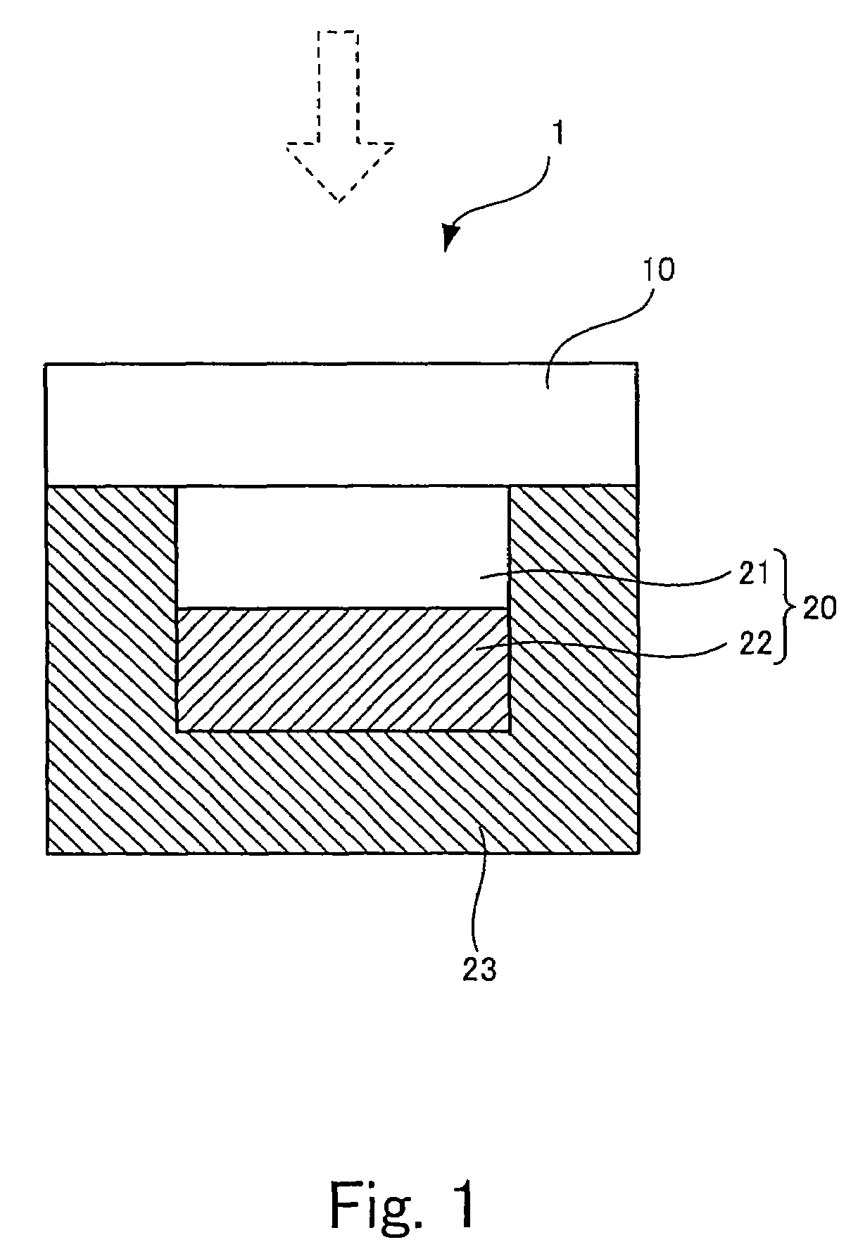
[0055]FIG. 1 is a schematic cross-sectional view of an image sensor unit 1 according to the embodiment of the present invention.

[0056]In the image sensor unit 1 according to the present embodiment, light from a subject represented by a dotted line is converged via an optical filter 10 onto a CCD 20, which is a solid-state image sensor and is disposed at the back of the optical filter 10, and is converted into an electric signal. The CCD 20 includes a microlens layer 21 for condensing the light from the subject for each pixel corresponding to each photodiode and a photodiode layer 22 of a photodiode array for converting the converged light into an electric signal. The microlens layer 21 and the photodiode layer 22 are held in a supporting layer 23.

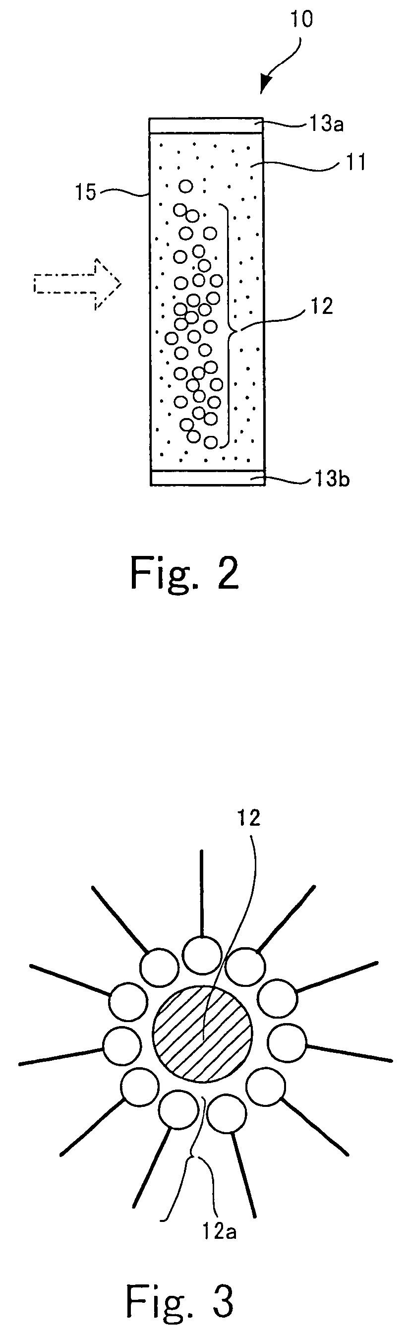
[0057]The structure of the optical filter 10 will be described below.

[0058]In the optical filter 10 according to this embodiment, th...

second embodiment

[0070]Another embodiment of the image taking apparatus according to the present invention will be described below. This embodiment provides a digital camera including the optical filter 10 described in the first embodiment.

[0071]FIG. 5 is an external perspective front view of a digital camera 100 as the embodiment of the image taking apparatus according to the present invention.

[0072]As shown in FIG. 5, the digital camera 100 is provided with a taking lens 101 in the front center, and an optical viewfinder object window 102 and a fill light emitting section 103 in the top front. The digital camera 100 is also provided with a power slide switch 104 and a release switch 150 on the top.

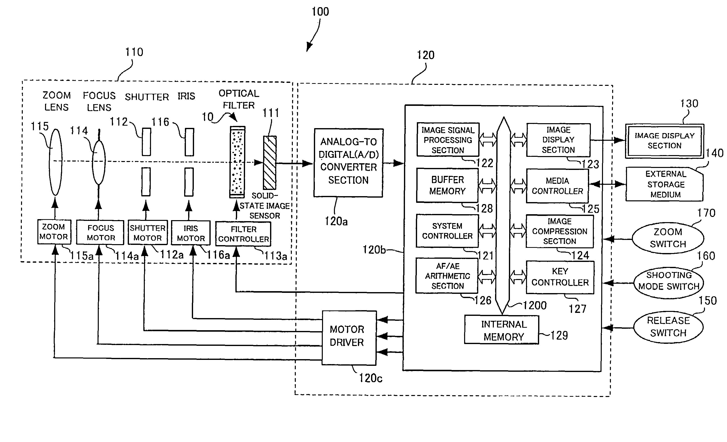
[0073]FIG. 6 is a schematic configuration diagram of the digital camera 100 shown in FIG. 5.

[0074]As shown in FIG. 6, the digital camera 100 according to the present embodiment is roughly divided into a photographic optical system 110 and a signal processing section 120. In addition to these, the digital...

third embodiment

[0086]Another embodiment of the image taking apparatus according to the present invention will be described as a third embodiment. This embodiment is a surveillance camera including the optical filter 10 according to the first embodiment.

[0087]FIG. 9 is a schematic configuration diagram of a surveillance camera 200.

[0088]The configuration of the surveillance camera 200 is almost the same as the digital camera 100 shown in FIG. 6. Thus, like components are denoted by like reference characters and will not be further explained.

[0089]While the digital camera is directly manipulated by an operator, the surveillance camera 200 is connected to a higher-level command computer 300 and is manipulated by an operator through the command computer 300. Thus, the surveillance camera 200 does not have switches or an external storage medium manipulated by the operator. A digital signal processing section 120d in a signal processing section 120′ also does not have a media controller or a key control...


PUM

PropertyMeasurementUnit
light transmittanceaaaaaaaaaa
thicknessaaaaaaaaaa
thicknessaaaaaaaaaa

Abstract

The present invention relates to an image sensor unit including an image sensor that generates an image signal and a filter, and to an image taking apparatus that receives light from a subject and generates an image signal. The image sensor unit and the image taking apparatus achieve excellent photographing through day and night. They are provided with a filter including a transparent layer that is transparent to light in a visible light region regardless of the state of an electric field and is transparent to light in a predetermined variable transparent region containing an infrared light region and / or an ultraviolet light region in response to the state of the electric field, and electrodes that generate the electric field in the transparent layer on the application of a voltage.

Description

BACKGROUND OF THE INVENTION[0001]1. Field of the Invention[0002]The present invention relates to an image sensor unit including an image sensor for generating an image signal and a filter, and to an image taking apparatus for generating an image signal from a received light from a subject.[0003]2. Description of the Related Art[0004]An image taking apparatus for taking pictures for 24 hours, such as a surveillance camera, has been known. The brightness of a subject to be photographed greatly varies between daytime and nighttime, in particular, in the outdoors. Thus, it is difficult to compensate such a large variation in the brightness by exposure control with a diaphragm used in a conventional camera.[0005]One countermeasure is to use a neutral-density filter and a highly sensitive image sensor. In the daytime, pictures are taken while the neutral-density filter reduces the brightness. In the nighttime, pictures are taken using direct light from a subject while the neutral-density ...

Claims


Application Information

Patent Timeline
Patent Type & Authority Patents(United States)
IPC IPC(8): H04N5/225B82Y20/00G02F1/13G02F1/133G02F1/1334G02F1/167G03B11/00H04N5/238H04N5/335H04N5/372
CPCH04N5/238G02F1/13342H04N23/75
Inventor KATO, TAKASHIMASUDA, TOMONORIMIYANO, HITOSHI
Owner FUJIFILM CORP
Why Eureka
Try Eureka