System and Method for an Automated Battery Arrangement

Inactive Publication Date: 2009-07-16
SYMBOL TECH INC
View PDF3 Cites 727 Cited by
  • Summary
  • Abstract
  • Description
  • Claims
  • Application Information

AI Technical Summary

Problems solved by technology

However, if the battery is improperly placed in the device, the energy may not be supplied to the device as no electrical connection is established.
Errors in placement of the power source in the device may cause this problem.
However, the portable nature of the device causes the battery to be inadvertently removed.
In addition, the battery may be jarr

Method used


Image

  • System and Method for an Automated Battery Arrangement
  • System and Method for an Automated Battery Arrangement
  • System and Method for an Automated Battery Arrangement

Examples


Embodiment Construction

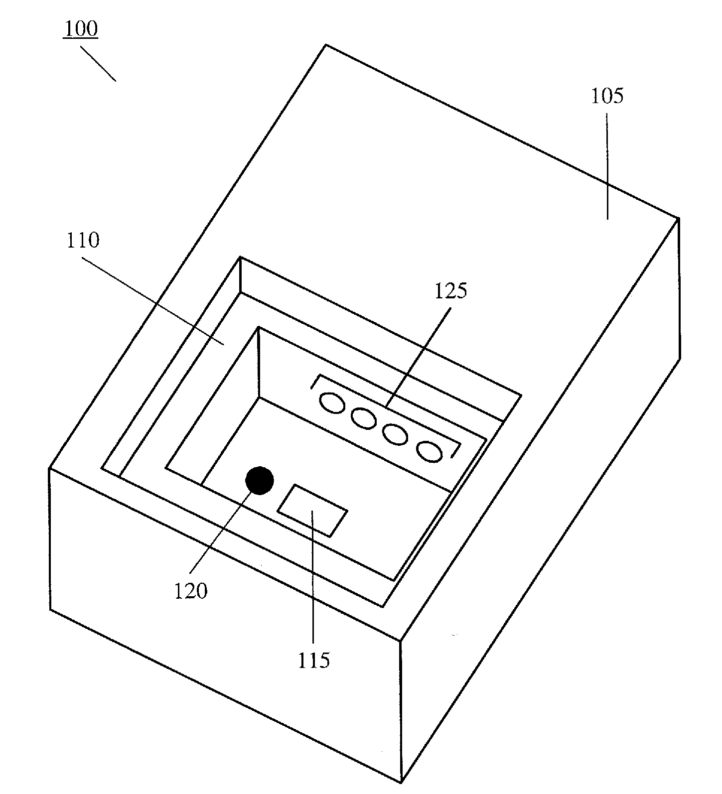
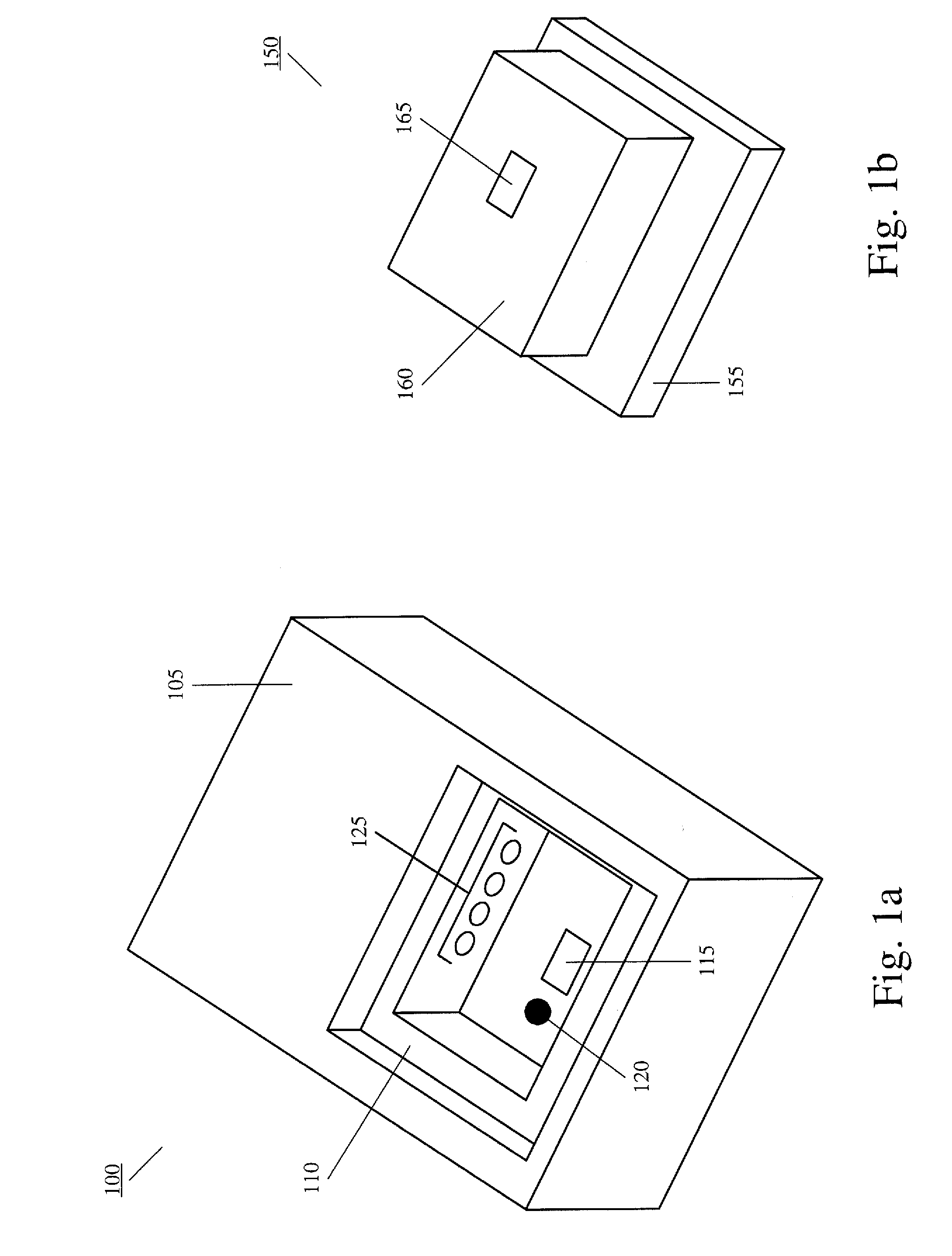
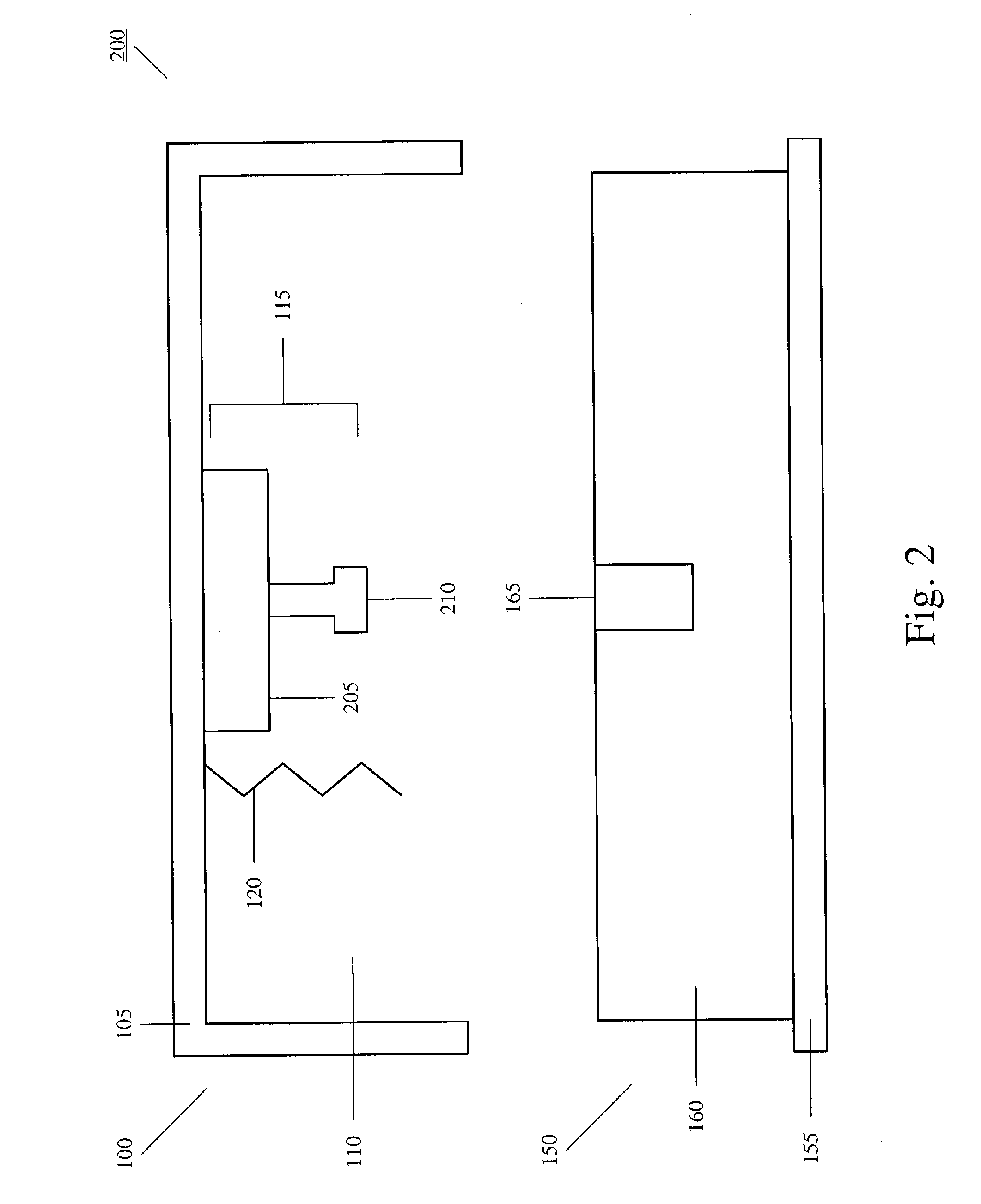
[0012]The exemplary embodiments of the present invention may be further understood with reference to the following description and the appended drawings, wherein like elements are referred to with the same reference numerals. The exemplary embodiments of the present invention describe an automated battery arrangement for a mobile unit (MU). The automated battery arrangement may be used for detection, insertion, retention, and ejection of a battery. The MU, the automated battery arrangement, and an associated method will be discussed in more detail below. It should be noted that the term “battery” in the following description may refer to any device that stores energy and provides the energy to a device. It should also be noted that the use of the MU is only exemplary. The exemplary embodiments of the present invention may apply to any electronic device which has a removable battery.

[0013]An MU may be equipped with a battery retention arrangement so that the battery is securely place...


PUM


Abstract

An electronic device comprises a housing and a battery arrangement. The housing has a recess which is shaped to receive a removable battery. The battery arrangement includes a locking mechanism automatically securing the battery within the recess from an initial position into a final position. The battery arrangement prevents a removal of the battery until a powering down procedure of the device is completed.

Description

FIELD OF THE INVENTION[0001]The present invention relates generally to a system and method for an automated battery arrangement. Specifically, the battery arrangement is used for detection, insertion, retention, and ejection of a battery.BACKGROUND[0002]Portable devices often utilize a removable power source (e.g., a battery, a capacitor, a supercapacitor, etc.) to provide the necessary energy to operate the device. The power source establishes an electrical connection to the device to supply the energy. The electrical connection may be established using, for example, a plurality of electrical contact points (e.g., pins) present on the device that couples to a corresponding plurality of electrical contact points on the power source. However, if the battery is improperly placed in the device, the energy may not be supplied to the device as no electrical connection is established. For example, if even one of the plurality of electrical contact points does not couple properly, the elec...

Claims


Application Information

Patent Timeline
IPC IPC(8): H01M2/10H01M50/202H01M50/244H01M50/247H01M50/264
CPCH01M2/1066H01M2/1022Y02E60/10H01M50/264H01M50/247H01M50/202H01M50/244
Inventor BALDWIN, TRAVISSPANO, ROBERT
Owner SYMBOL TECH INC
Why Eureka
Try Eureka