Lateral pipe lining material and lateral pipe lining method

a technology of lateral pipe lining and lateral pipe, which is applied in the direction of shaft lining, shaft equipment, mechanical equipment, etc., can solve the problems of lining failure, high cost, and high labor intensity of above-conventional methods, and achieves high-quality lateral pipe lining, easy pressing, and simple configuration

Inactive Publication Date: 2009-07-23
SHONAN GOSEI JUSHI SEISAKUSHO KK
View PDF11 Cites 7 Cited by
  • Summary
  • Abstract
  • Description
  • Claims
  • Application Information

AI Technical Summary

Benefits of technology

[0009]It is an object of the present invention to provide a lateral pipe lining material and a lateral pipe lining method which are capable of excellently drawing the lateral pipe lining material into a lateral pipe to perform high-quality lining of the lateral pipe.
[0013]According to the invention, the collar of the lateral pipe lining member is pushed up by the pushing-up member and brought into close contact with the lateral pipe opening periphery of the main pipe, thus allowing a high-quality lateral pipe lining to be realized.
[0014]Furthermore, even when the bent lateral pipe causes wrinkles to be generated in a resin impregnated in the tubular resin absorbing material, the wrinkles can be easily pressed out by the simple configuration, whereby uniform lining can be performed on the lateral pipe.

Problems solved by technology

However, the above conventional method has drawbacks.
That is, in the above conventional lateral pipe lining method, it is necessary that the working robot is introduced in the main pipe to set the collar of the lateral pipe lining material at a location at which the main pipe intersects with the lateral pipe, which requires much time and labor.
This disadvantageously necessitates a pressure bag for everting the lateral pipe lining material.
However, another problem arises if the lateral pipe extends from the main pipe and is bent on the way to the ground.
When the lateral pipe lining material is pulled aboveground, the bent portions of the lateral pipe interfere with good close contact between the collar of the lateral pipe lining material and the lateral pipe opening periphery of the main pipe, thus causing a lining failure.
Particularly, high degree of bending of the lateral pipe or a large number of times of the bending causes the serious problem.
Still another problem is that, if the degree of bending of the lateral pipe is high or the number of times of the bending is large, wrinkles occur in the resin impregnated in the lateral pipe lining material, thereby making it impossible to achieve uniform lining.

Method used


Image

  • Lateral pipe lining material and lateral pipe lining method
  • Lateral pipe lining material and lateral pipe lining method
  • Lateral pipe lining material and lateral pipe lining method

Examples


Embodiment Construction

[0036]Best modes of carrying out the present invention will be described in more detail using various embodiments with reference to the accompanying drawings.

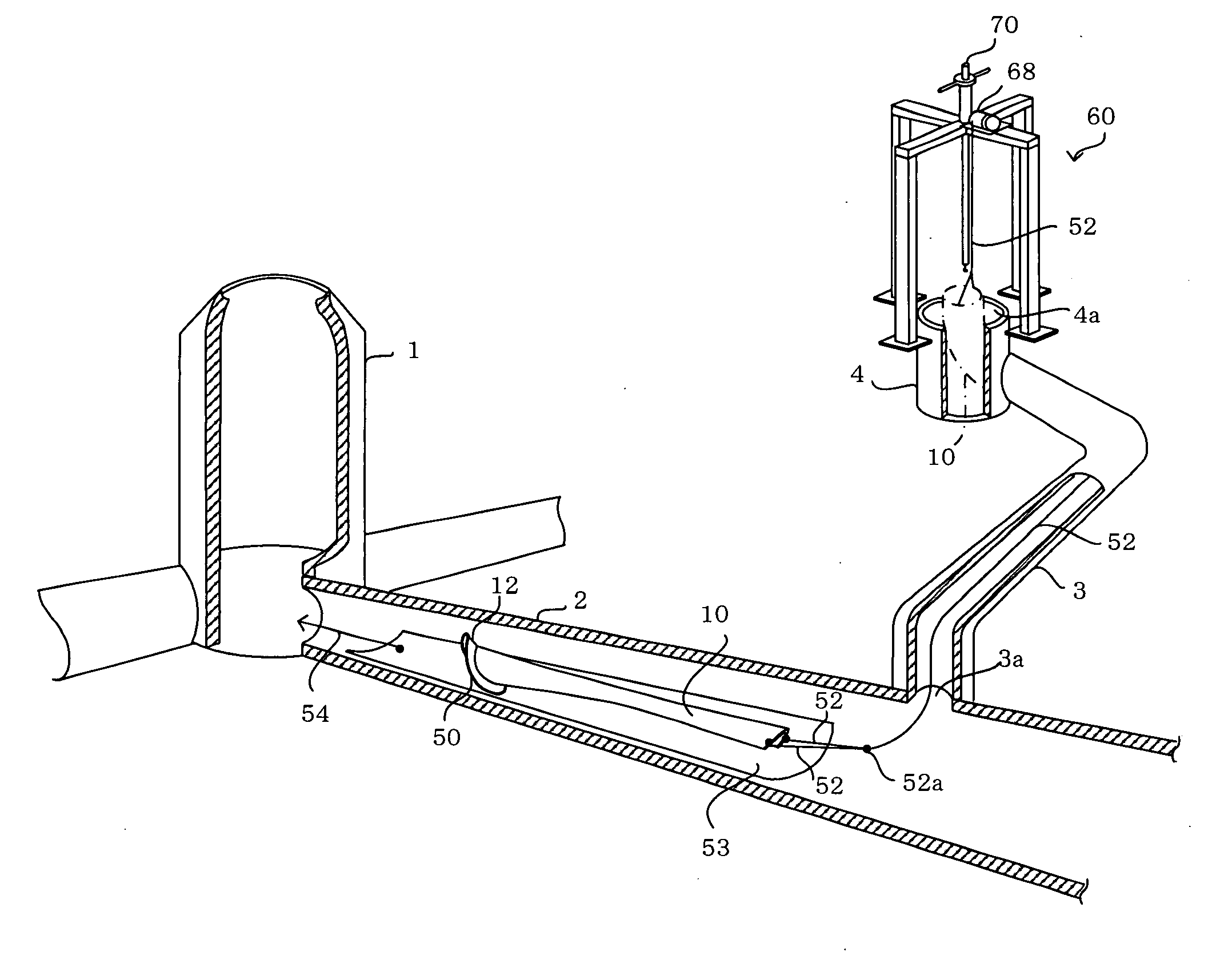
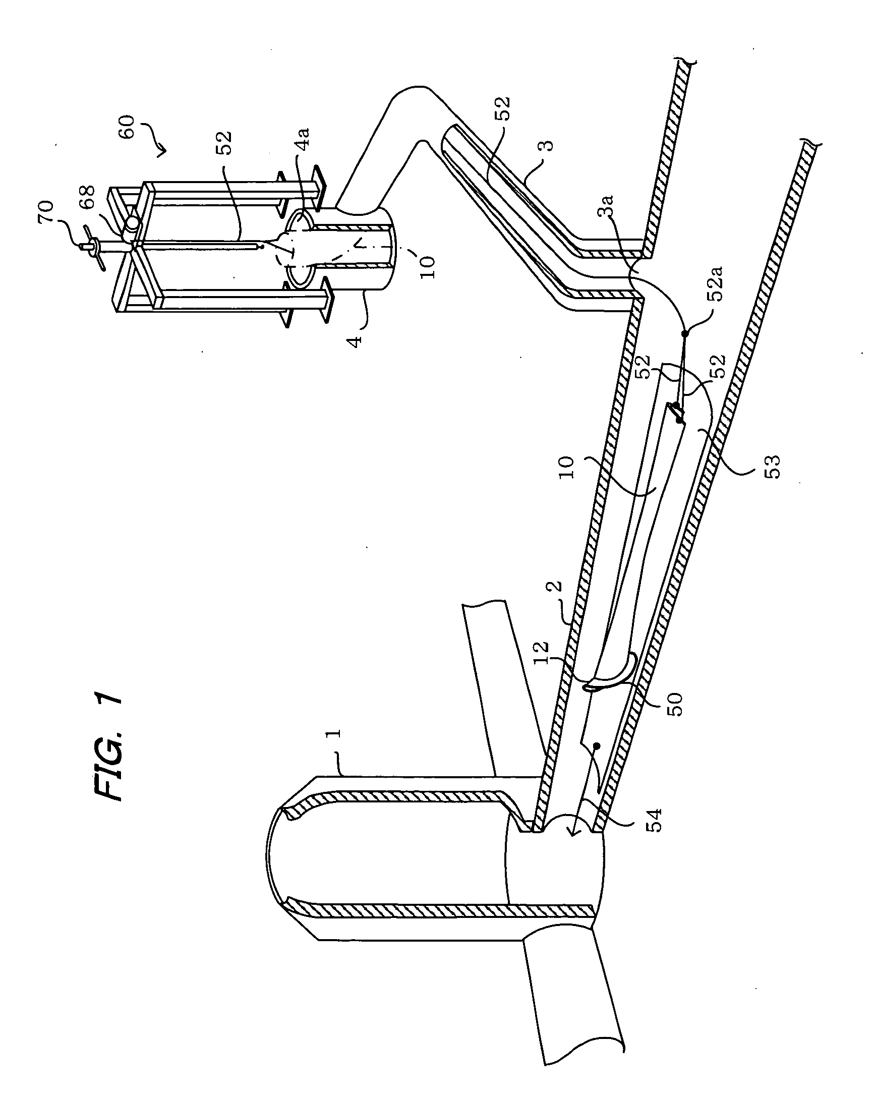
[0037]FIG. 1 is an illustrative view showing the state where a lateral pipe lining material 10 carried into a main pipe 2 from a manhole 1 is drawn into a lateral pipe 3 according to an embodiment of the present invention.

[0038]A lifting apparatus 60 disposed on the ground is used to wind up a drawing rope 52 which is attached to an end of the lateral pipe lining material 10 in order to lift and draw the lateral pipe lining material 10 into the lateral pipe 3 through a box 4 above the ground. In FIG. 1, the lateral pipe lining material 10 lifted above the ground is shown imaginarily by a dash and dotted line.

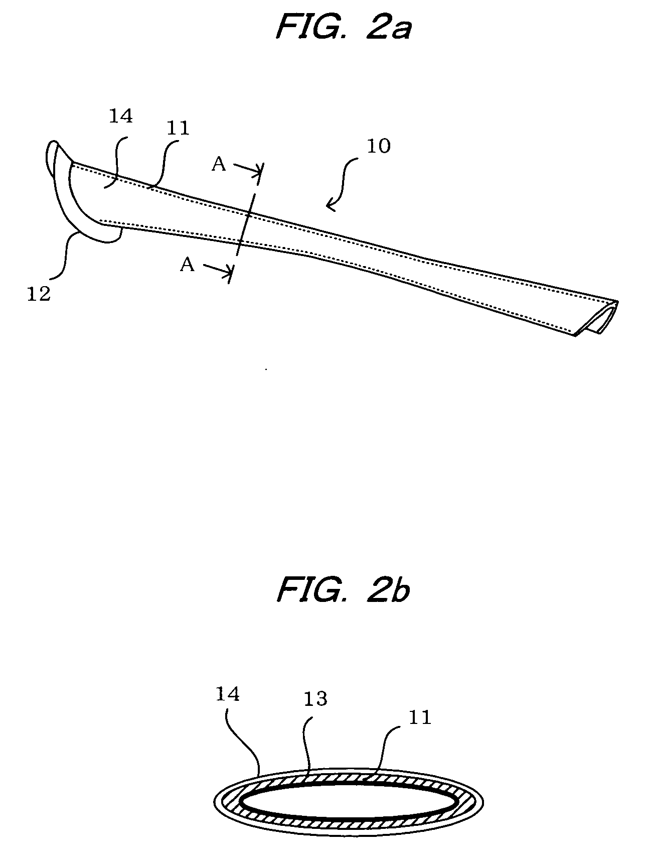
[0039]The lateral pipe lining material 10, as shown in FIGS. 2a and 2b, is comprised of a flexible tubular resin-absorbing material 11 of a non-woven fabric. The lining material 10 has a flange-like collar 12 attached at it...


PUM


Abstract

A lateral pipe lining material having a tubular resin-absorbing material impregnated with a thermosetting resin is inserted through a main pipe into the lateral pipe. The lateral pipe lining material is provided with a pushing-up member to push up a collar formed at its end of the lateral pipe lining material. When the lateral pipe lining material is drawn into the lateral pipe to the extent that the collar reaches an opening of the lateral pipe, the pushing-up member is lifted to bring the collar into close contact with the lateral pipe opening periphery of the main pipe. The lateral pipe lining material is then expanded and a heating medium is applied thereto to cure the resin impregnated in the tubular resin-absorbing material. The lateral pipe lining material can be drawn smoothly into the lateral pipe even when it is bent, enabling the lateral pipe to be lined with a high quality.

Description

BACKGROUND OF THE INVENTION[0001]1. Field of the Invention[0002]The present invention relates to a lateral pipe lining material and a lateral pipe lining method, and more particularly to the lateral pipe lining material to repair a lateral pipe extending from a main pipe toward the ground and to the lateral pipe lining method for lining the lateral pipe using the lateral pipe lining material.[0003]2. Description of the Related Art[0004]Conventionally, pipe lining methods used when a pipe such as a sewer pipe or the like buried under the ground is aged have been known which repair the pipe by performing lining on its inner circumferential surface without digging up the pipe from underground.[0005]For example, Japanese Patent Application Laid-open No. 1992-355115 discloses a method for lining a lateral pipe that branches off from a main pipe, wherein a collar formed at an end of a lateral pipe lining material that is placed inside a pressure bag is set on a set nozzle of a working rob...

Claims


Application Information

Patent Timeline
Patent Type & Authority Applications(United States)
IPC IPC(8): F16L55/16
CPCF16L55/179
Inventor KAMIYAMA, TAKAOKANETA, KOJIFUJII, KENJI
Owner SHONAN GOSEI JUSHI SEISAKUSHO KK
Why Eureka
Try Eureka