
Lateral pipe lining method and lateral pipe lining apparatus

Inactive Publication Date: 2012-05-03
SHONAN GOSEI JUSHI SEISAKUSHO KK
View PDF4 Cites 2 Cited by
  • Summary
  • Abstract
  • Description
  • Claims
  • Application Information

AI Technical Summary

Benefits of technology

[0011]It is therefore an object of the present invention to provide a lateral pipe lining method and apparatus being capable of improving joining of the lateral pipe lining material and the main pipe lining material to provide high-quality lining of the lateral pipe.
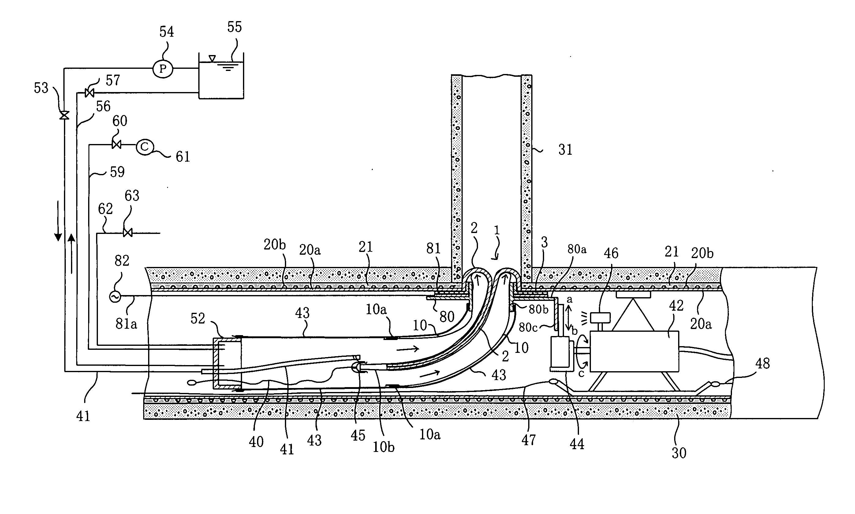
[0014]According to the present invention, the main pipe is lined using a main pipe lining material composed of a resin pipe made of thermoplastic resin, or a main pipe lining material composed of a flexible tubular resin-absorbing material covered by a plastic film of thermoplastic resin. The lateral pipe lining material is formed with a flange of a material capable of being welded to the thermoplastic resin of the resin pipe or of the plastic film of the main pipe lining material. The thermoplastic resin of the flange of the lateral pipe lining material and the thermoplastic resin of the resin pipe or of the plastic film are heated for plastic welding to integrally join the flange of the lateral pipe lining material with the main pipe lining material. This allows the flange of the lateral pipe lining material to be reliably joined with ease with the main pipe lining material, thus preventing inflow of underground water together with sediment into the main pipe from the section where the lateral pipe and the main pipe intersect.
[0015]Preferably, the thermoplastic resin of the resin pipe or of the plastic film of the main pipe lining material and the thermoplastic resin of the flange of the lateral pipe lining material are the same resin and are soft, so that the flange reliably comes into close contact with the main pipe lining material, thus allowing plastic welding to be readily and reliably carried out.

Problems solved by technology

Therefore, drawbacks are presented in that manufacturing costs are high, and, particularly in cases where the flange of the lateral pipe lining material is rigid, close contact may not be sufficient, so that there is insufficient joining between the lateral pipe lining material and the main pipe lining material.

Method used


Image

  • Lateral pipe lining method and lateral pipe lining apparatus
  • Lateral pipe lining method and lateral pipe lining apparatus
  • Lateral pipe lining method and lateral pipe lining apparatus

Examples


Embodiment Construction

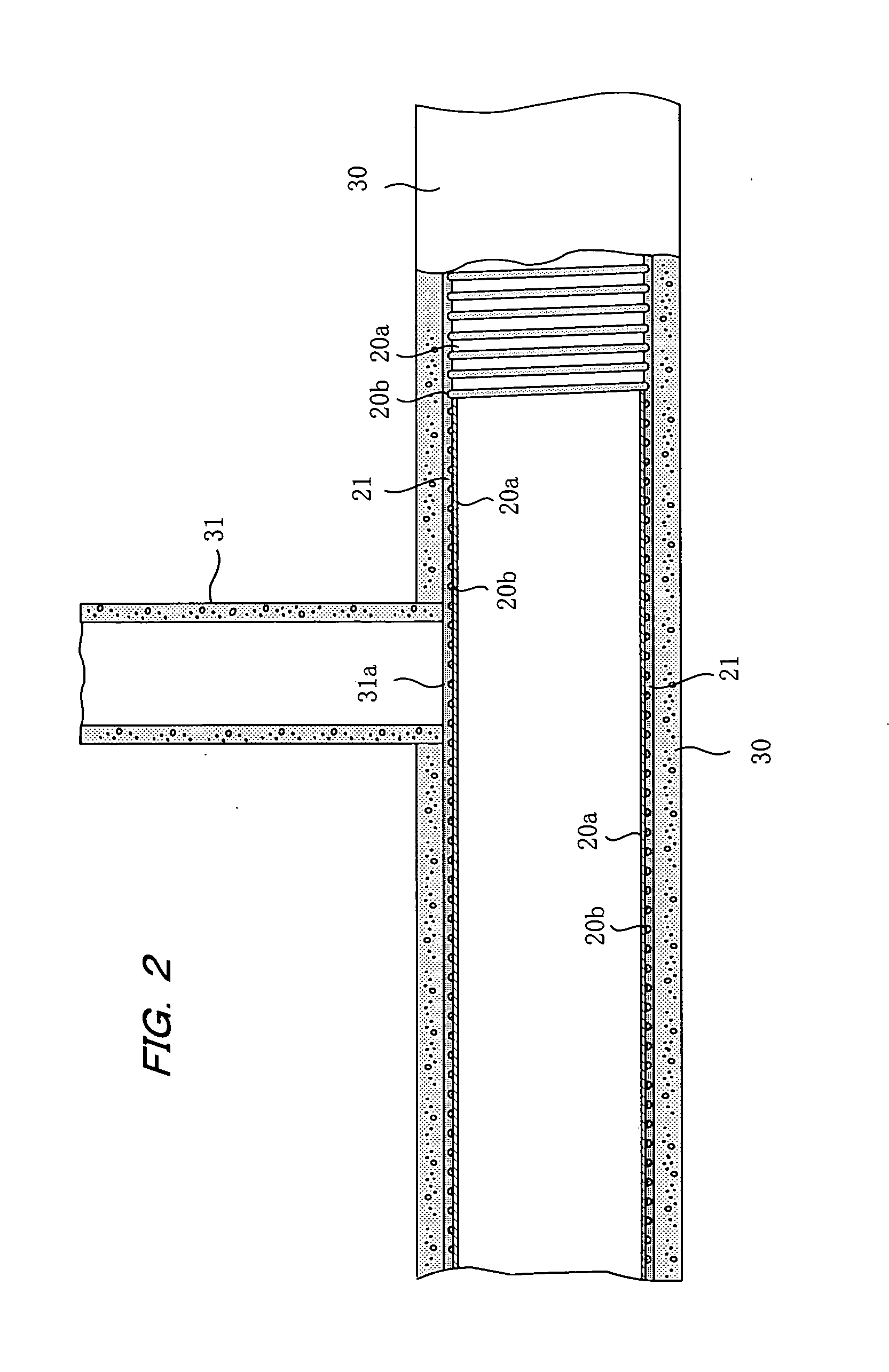
[0038]The present invention will now be described in detail based on the attached drawings with reference to the embodiments of a lateral pipe lining material for lining a lateral pipe that branches from a main pipe, and a lateral pipe lining method as well as a lateral pipe lining apparatus. The main pipe is an existing pipe such as a sewer pipe, water supply pipe, agricultural water channel, or the like, and the lateral pipe is a pipe which is attached to the main pipe and branches therefrom to the ground.

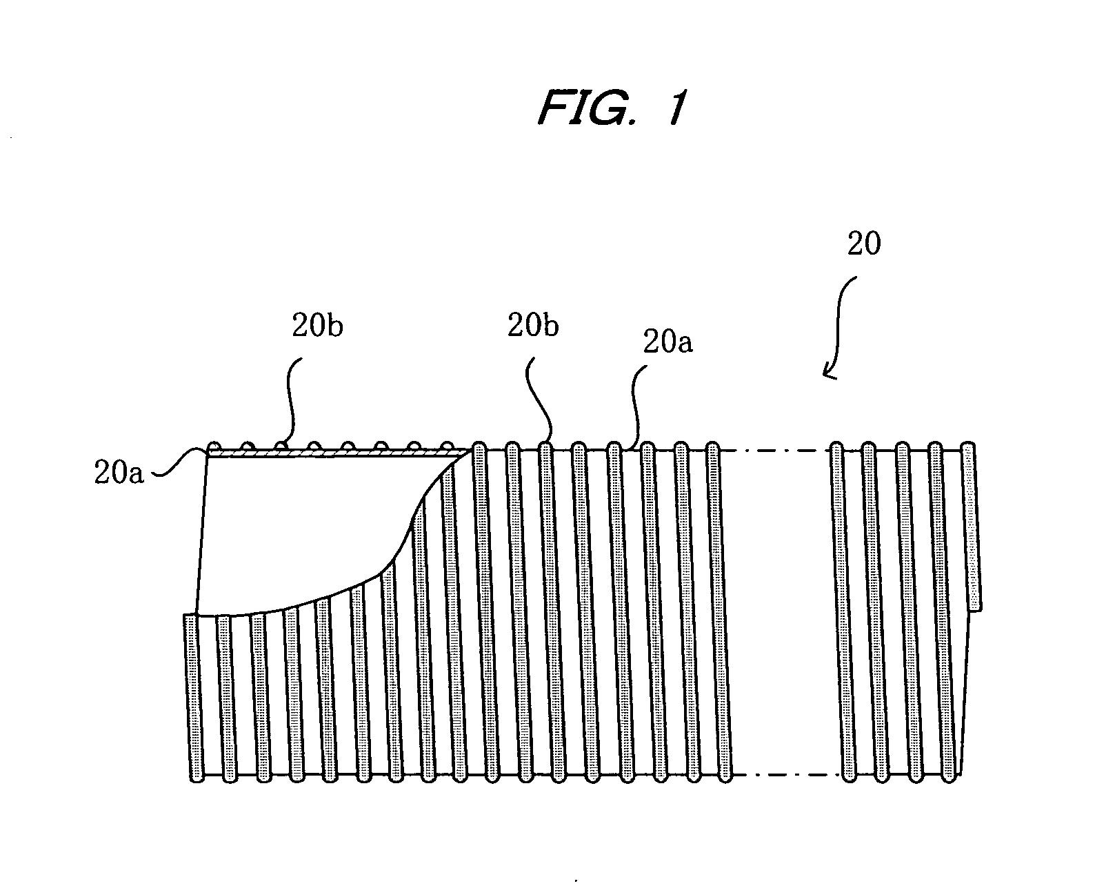
[0039]In FIG. 1, a main pipe lining material 20 for lining a main pipe is shown partially in cross section. The main pipe lining material 20 comprises a tubular resin pipe 20a having an outside diameter smaller than the inside diameter of the main pipe, and a reinforcing protruding rib 20b that is wound in a spiral pattern about the outside wall of the resin pipe 20a. The resin pipe 20a is formed, for example, of a soft thermoplastic resin such as polyethylene, polypropylene, or ...


PUM

PropertyMeasurementUnit
Thermoplasticityaaaaaaaaaa

Abstract

A main pipe is lined by a main pipe lining material comprising a resin pipe made of a thermoplastic resin. A flange of a lateral pipe lining material is formed of a material capable of being welded to the thermoplastic resin of the resin pipe of the main pipe lining material. The thermoplastic resins of the flange of the lateral pipe lining material and the resin pipe are heated for plastic welding by a heater to integrally join the flange of the lateral pipe lining material with the main pipe lining material. This prevents the ingress of underground water together with sediment into the main pipe from the section where the lateral pipe and the main pipe intersect.

Description

BACKGROUND OF THE INVENTION[0001]1. Field of the Invention[0002]The present invention relates to a lateral pipe lining method and apparatus in which a lateral pipe lining material for lining a lateral pipe is inserted into the lateral pipe from a lateral pipe opening of a main pipe, which is lined using a main pipe lining material composed of a resin pipe made of thermoplastic resin, or using a main pipe lining material composed of a tubular resin-absorbing material covered with a plastic film of thermoplastic resin.[0003]2. Description of the Prior Art[0004]In cases where pipelines such as sewer pipes buried underground are aged, a pipe lining method for lining the inner circumferential surface of a pipeline is known to make repairs without having to excavate the pipeline from the ground.[0005]For example, JP 2008-25761 A discloses a method for lining a main pipe using a main pipe lining material which comprises a resin pipe composed of a thermoplastic resin and a reinforcing protr...

Claims


Application Information

Patent Timeline
IPC IPC(8): B29C63/34
CPCF16L55/179F16L55/1651F16L55/265B29C63/34E03F7/00
Inventor KAMIYAMA, TAKAOKANETA, KOJIFUJII, KENJITANAKA, FUMINORI
Owner SHONAN GOSEI JUSHI SEISAKUSHO KK
Learn More