Two-Wheeled In-Line Walker

a two-wheeled, in-line walker technology, applied in the direction of bicycles, manufacturing tools, transportation and packaging, etc., can solve the pain of prolonged standing and/or walking with full weight bearing on the lower extremities, and achieve the effect of providing lateral stability, prolonging standing, and full weight bearing

Inactive Publication Date: 2009-08-06
ZIMMERMAN PAUL JAMES
View PDF6 Cites 22 Cited by
  • Summary
  • Abstract
  • Description
  • Claims
  • Application Information

AI Technical Summary

Benefits of technology

[0051]This invention is a supportive medical walking aid for indoor use consisting of two small caster wheels located in-line with adjustable, collapsible seat and handle bars. The intended user is a person with lower extremity problems such that prolonged standing and / or walking with full weight bearing on the lower extremities is painful. Because the invention provides no lateral stabilization, the user must be capable of providing lateral stability with lower extremities. The intended application locations would be stores, shopping malls, airports and public buildings and especially areas where bicycles are prohibited but wheelchairs and walkers are allowed. The invention would allow prolonged comfortable walking, standing and resting as is required for shopping, running errands browsing about and accompanying others in similar activities. Although the invention provides relief for the user by taking body weight off the lower extremities which could be of some temporary therapeutic or rehabilitative value, the device's main use will be in allowing an afflicted person to lead a more normal life style by making chronic problems like arthritis of the knees, ankles and feet, less intrusive on lifestyle.

Problems solved by technology

The intended user is a person with lower extremity problems such that prolonged standing and / or walking with full weight bearing on the lower extremities is painful.

Method used


Image

  • Two-Wheeled In-Line Walker
  • Two-Wheeled In-Line Walker
  • Two-Wheeled In-Line Walker

Examples


Embodiment Construction

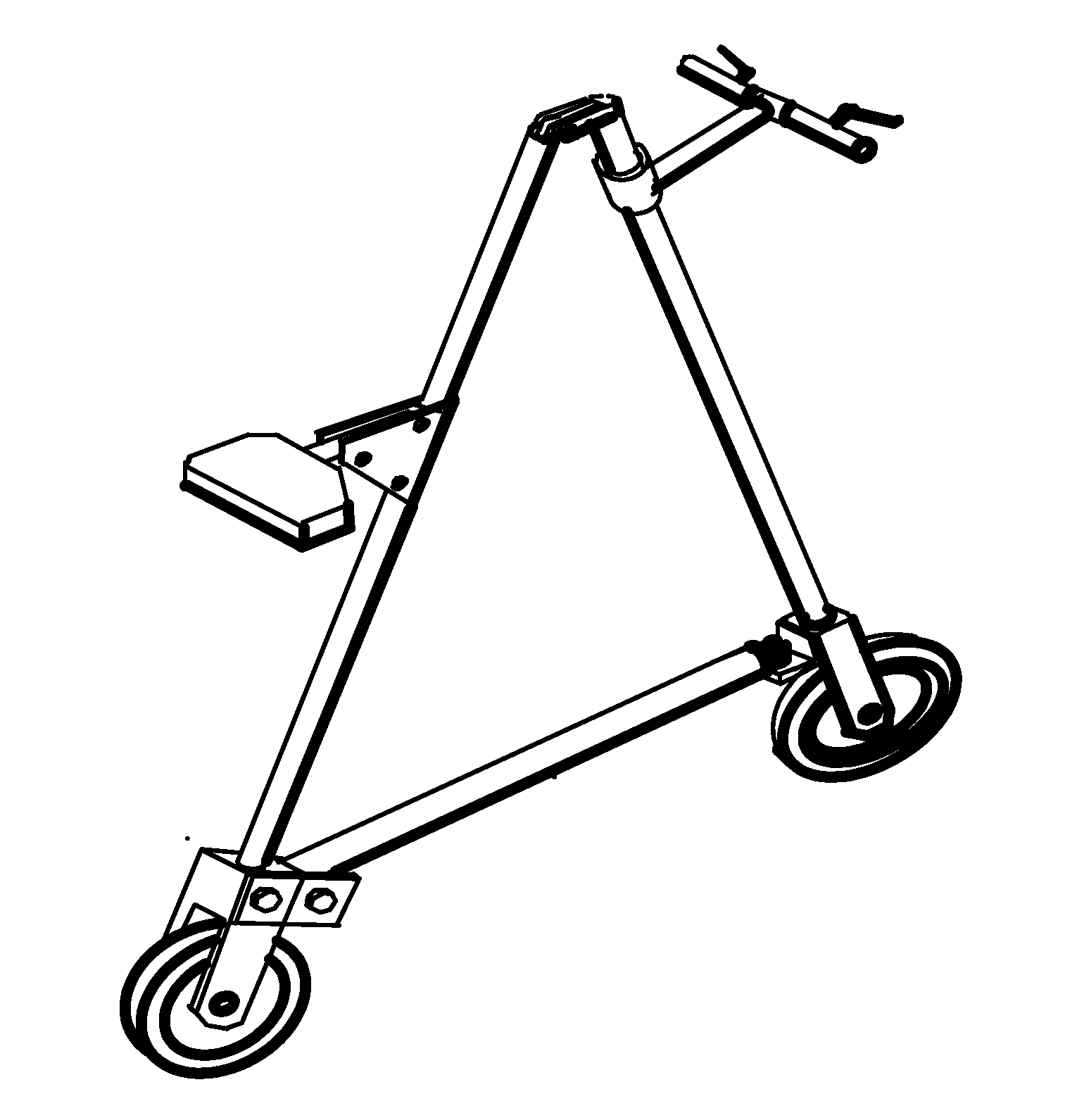
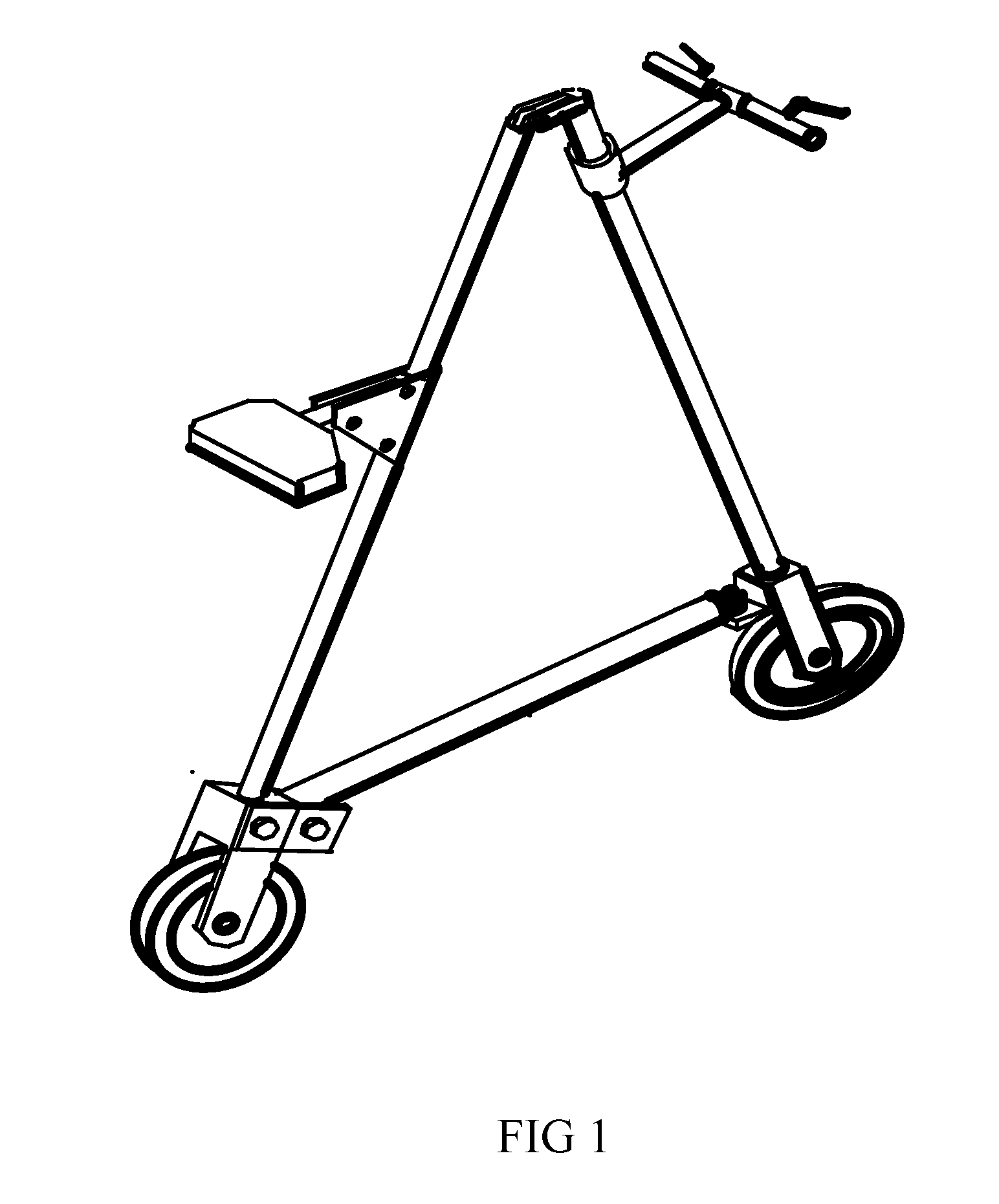
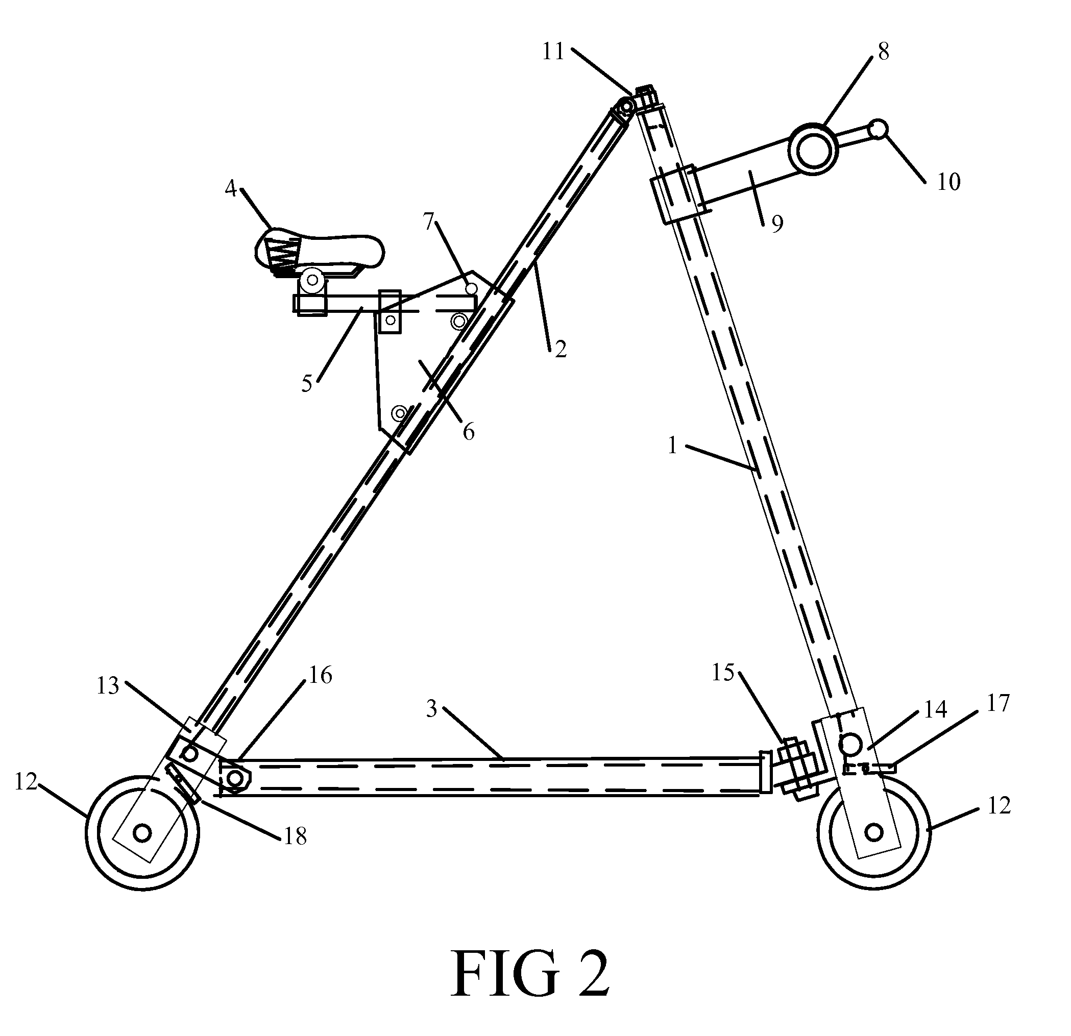
[0054]In the preferred embodiment as shown in FIG. 1 and FIG. 2, the frame consists of three members which are connected such that foldability and collapsibility are enabled. The forward member 1 is the steering member and as such is mounted so it can rotate about its longitudinal axis and has handlebar assembly and caster wheel assembly attached. The rear member 2 has the seat assembly attached and caster assembly mounted to the lower end. The horizontal member 3 connects the lower end of the front member to the lower end of the rear member. The horizontal member is pivotally mounted to the rear member and rotationally and releasably attached to the front member. Disconnecting the front of the horizontal member allows it to pivot upwards parallel to the rear member to facilitate foldability of the structure. The pivot attachment to the rear caster fork provides rotational stiffness to the rear tube, caster and seat assembly.

[0055]In the preferred embodiment, the seat 4 assembly is ...


PUM


Abstract

A supportive medical walking aid for indoor use consisting of two small caster wheels located in-line with adjustable, collapsible seat and handle bars. The invention is viewed as a long term lifestyle enhancing tool rather than a temporary rehabilitative or therapeutic device. Locomotion is provided only by a walking action of the infirmed person. The device is collapsible and light weight for easy transport and storage. Seat and handle bar placement geometry to facilitate comfortable walking, standing and forward leaning as in easy resting. Frame consisting of a front near vertical steering member with caster wheel rotatably attached; a rear member with caster wheel rotatably attached and a horizontal member vertically pivotally attached to the rear member and rotatably and releasably attached to the lower end of the front member. The adjustable, collapsible seat is attached to the rear member and the handlebar assembly is attached to the front member. A hinge connects the top of the rear member to the front member in a manner allowing rotation of the front steering member. Safety brakes are provided on both front and rear casters.

Description

CROSS REFERENCE TO RELATED APPLICATIONS[0001]Not ApplicableFEDERALLY SPONSORED RESEARCH[0002]Not ApplicableSEQUENCE LISTING OR PROGRAM[0003]Not ApplicableBACKGROUND[0004]1. Field of the Invention[0005]The present invention relates to walking aid devices and more particularly to a new walking aid device which allows the user to take most or all of the body weight off the lower extremities while in a standing position and allowing increased mobility through direct foot contact with the surface using a walking motion and is aimed at long term indoor use where surfaces are smooth and higher speed devices like bicycles are prohibited. While this invention may have rehabilitative and therapeutic value its primary intended use is by persons with chronic lower limb problems who wish to lead a more normal life style without corrective surgery.[0006]2. Prior Art[0007]The use of walking aid devices is known in the prior art. U.S. Pat. Nos. 6,318,392; 5,887,887 describe walking carts utilizing ...

Claims


Application Information

Patent Timeline
Patent Type & Authority Applications(United States)
IPC IPC(8): A61H3/04B60B33/00
CPCA61H3/04A61H2003/046A61H2201/0161Y10T16/1853B62K3/002B62K3/16A61H2201/1633
Inventor ZIMMERMAN, PAUL JAMES
Owner ZIMMERMAN PAUL JAMES
Why Eureka
Try Eureka