Universal Assembly for Top and Bottom Latches

Active Publication Date: 2009-08-06
I TEK METAL MFG
View PDF10 Cites 21 Cited by
  • Summary
  • Abstract
  • Description
  • Claims
  • Application Information

AI Technical Summary

Benefits of technology

[0021]All figures are drawn for ease of explanation of the basic teachings of the present invention only; the extensions of the Figures with respect to number, position, relationship, and dimensions of the parts to form the preferred embodiment will be explained or will be within the skill of the art after the following teachings of the present invention have been read and understood. Further, the exact dimensions and dimensional proportions to conform to specific force, weight, strength, and similar requirements will likewise be within the skill of the art after the fol

Problems solved by technology

However, the resultant top and bottom latches are still too complicated and have

Method used


Image

  • Universal Assembly for Top and Bottom Latches
  • Universal Assembly for Top and Bottom Latches
  • Universal Assembly for Top and Bottom Latches

Examples


Embodiment Construction

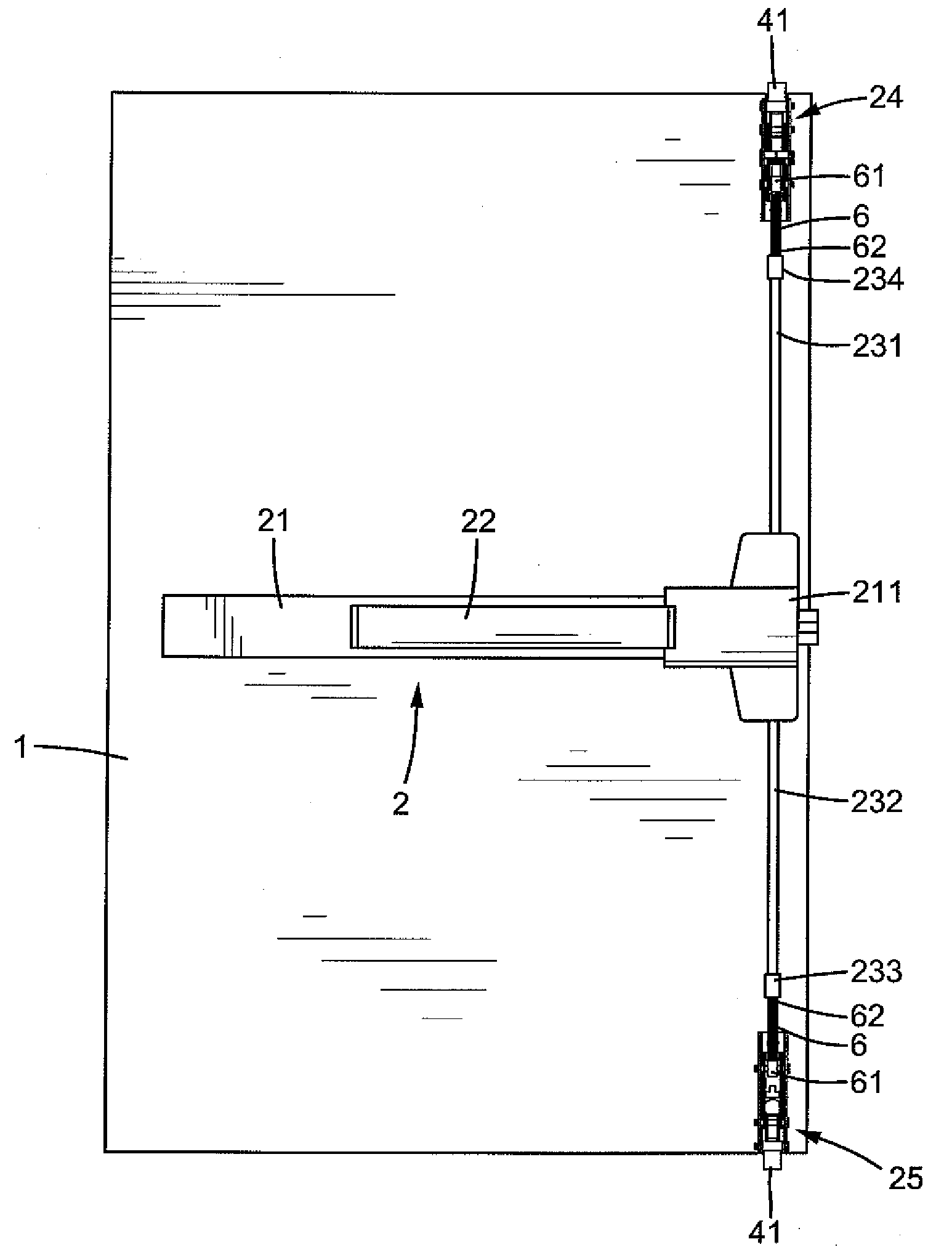
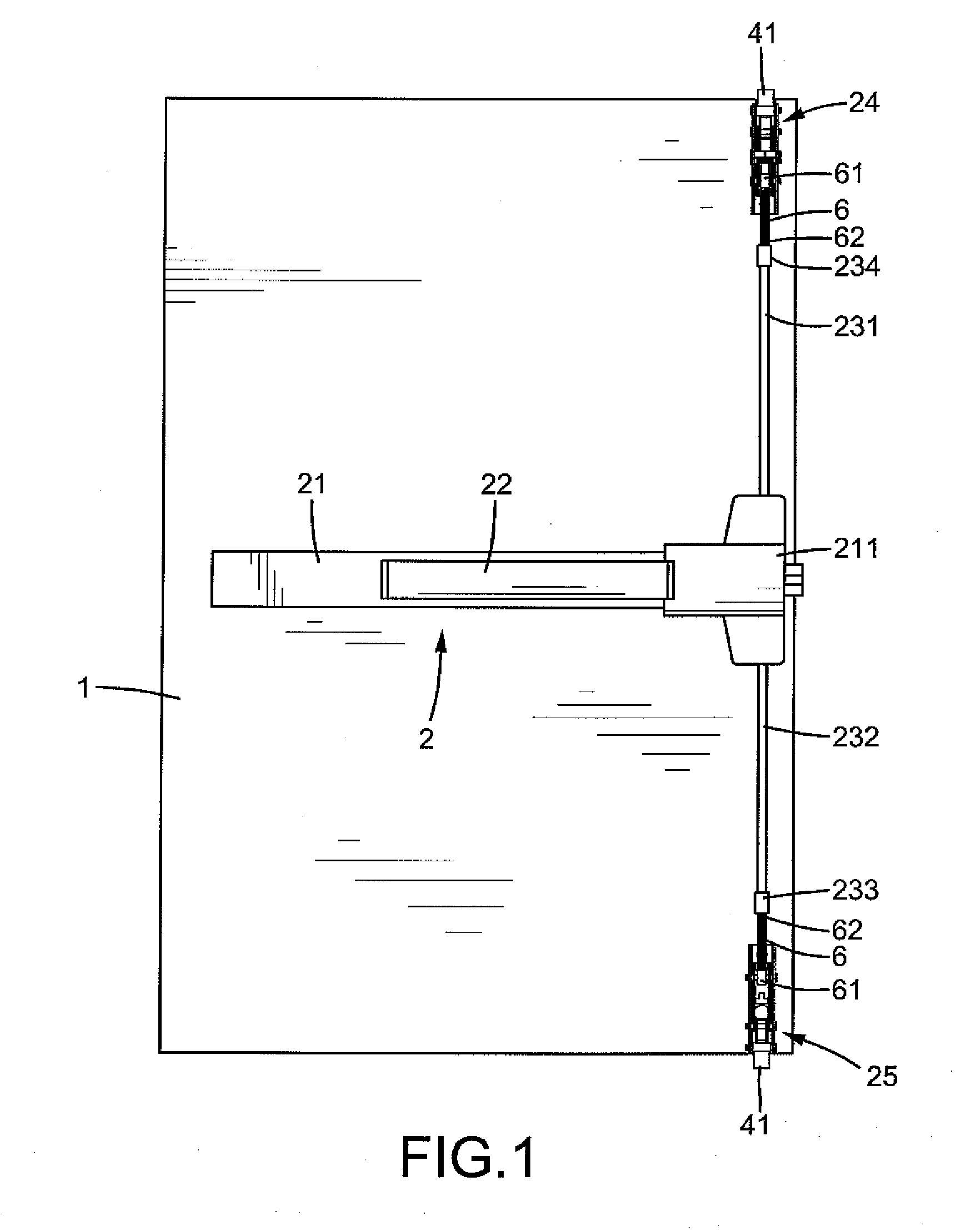
[0023]FIG. 1 shows a panic device 2 mounted to a panic exit door 1 or the like and includes a housing 21 mounted to the door 1, a touch bar 22 mounted outside the housing 21 for manual operation, and a transmission mechanism (not shown) mounted in an end 211 of the housing 21. The panic device 2 further includes a top latch 24 and an upper vertical rod 231 having a lower end coupled with the transmission mechanism and an upper end 234 coupled with the top latch 24. The panic device 2 further includes a bottom latch 25 and a lower vertical rod 232 having an upper end coupled with the transmission mechanism and a lower end 233 coupled with the bottom latch 25. When the touch bar 22 is pressed, the upper and lower vertical rods 231 and 232 are moved toward each other in a vertical direction to unlatch the top and bottom latches 24 and 25. The transmission mechanism can be of any desired form as conventional including but not limited to of a commercially available type.

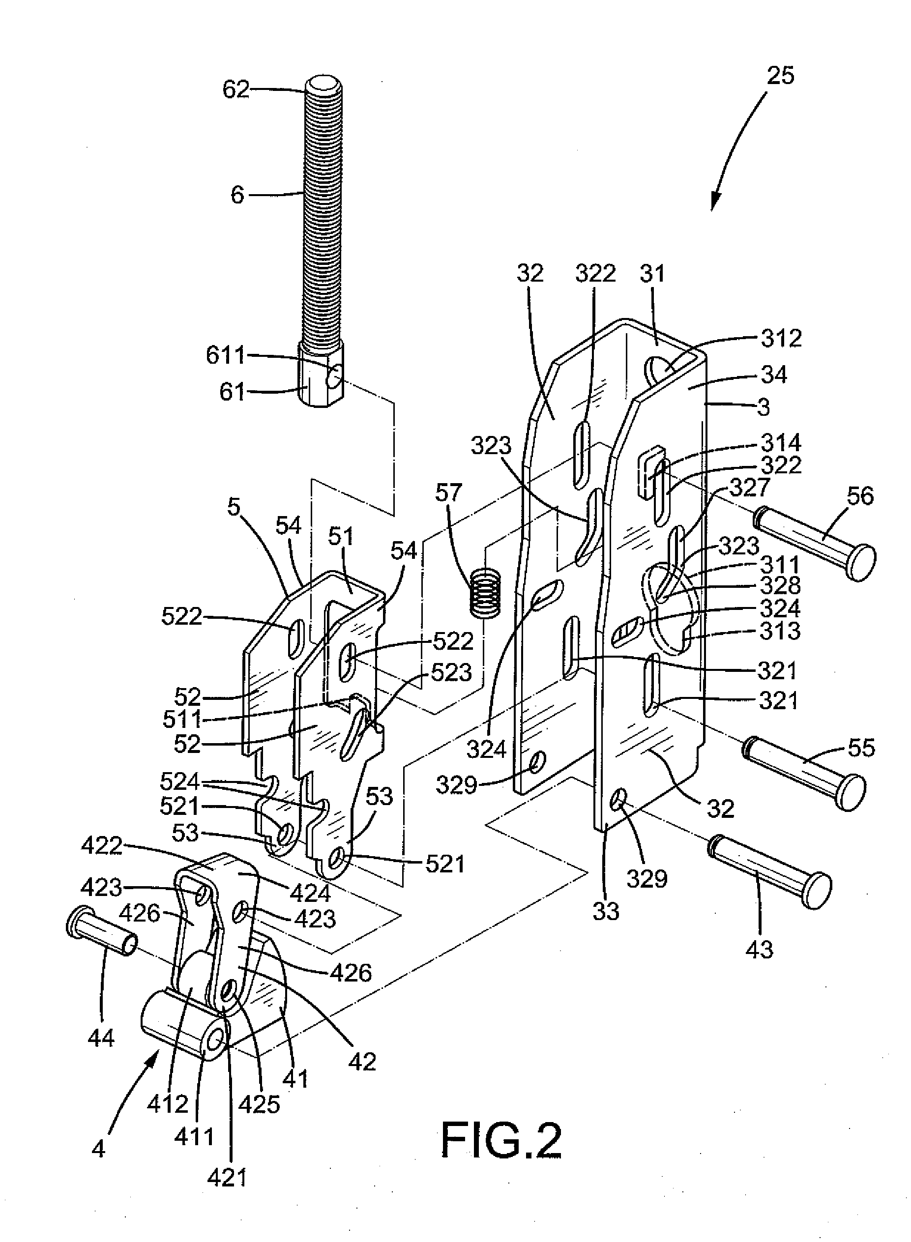
[0024]FIGS. 2 and...


PUM


Abstract

A latch assembly includes a base mounted to a door and a latch bolt having a latch pivotably connected to the base. The latch bolt further includes a link pivotably connected to the latch and the base. A follower plate is pivotably connected to the link, allowing pivotal movement of the follower plate and the link relative to the base and allowing relative pivotal movement between the follower plate and the link. A linking rod is coupled with the follower plate to move therewith. When the linking rod moves in a vertical direction, the follower plate moves together with the linking rod to pivot the latch between a latching position and an unlatching position. The latch assembly can be utilized as a surfaced-type or concealed-type bottom latch. After adding some parts, the latch assembly can be converted into a surfaced-type or concealed-type top latch.

Description

BACKGROUND OF THE INVENTION[0001]The present invention relates to a universal assembly and, more particularly, to a universal assembly for top and bottom latches for a panic exit door or the like.[0002]Panic exit doors include horizontal type latches and vertical type latches. Vertical type latches include a top latch and a bottom latch, wherein the top and bottom latches include concealed type and surfaced type according to the way they are mounted. Conventionally, concealed-type top and bottom latches are different from one another and different from surfaced-type top and bottom latches that are also different from one another. U.S. Pat. No. 4,974,890 to Cohrs discloses a universal assembly including components and parts interchangeable between, for being common to, a top latch and a bottom latch in vertical-rod exit devices. Simply by adding a few discrete parts to the assembly, the same becomes, selectively, a top latch or a bottom latch. However, the resultant top and bottom la...

Claims


Application Information

Patent Timeline
IPC IPC(8): E05C3/12E05C3/02
CPCE05B65/1006E05B63/0056Y10T292/091Y10T292/1043Y10T292/0909Y10T292/1051Y10T292/0908
Inventor SHEN, CHUN-MENG
Owner I TEK METAL MFG
Why Eureka
Try Eureka