

Flexibly bended boot for optical fiber connector
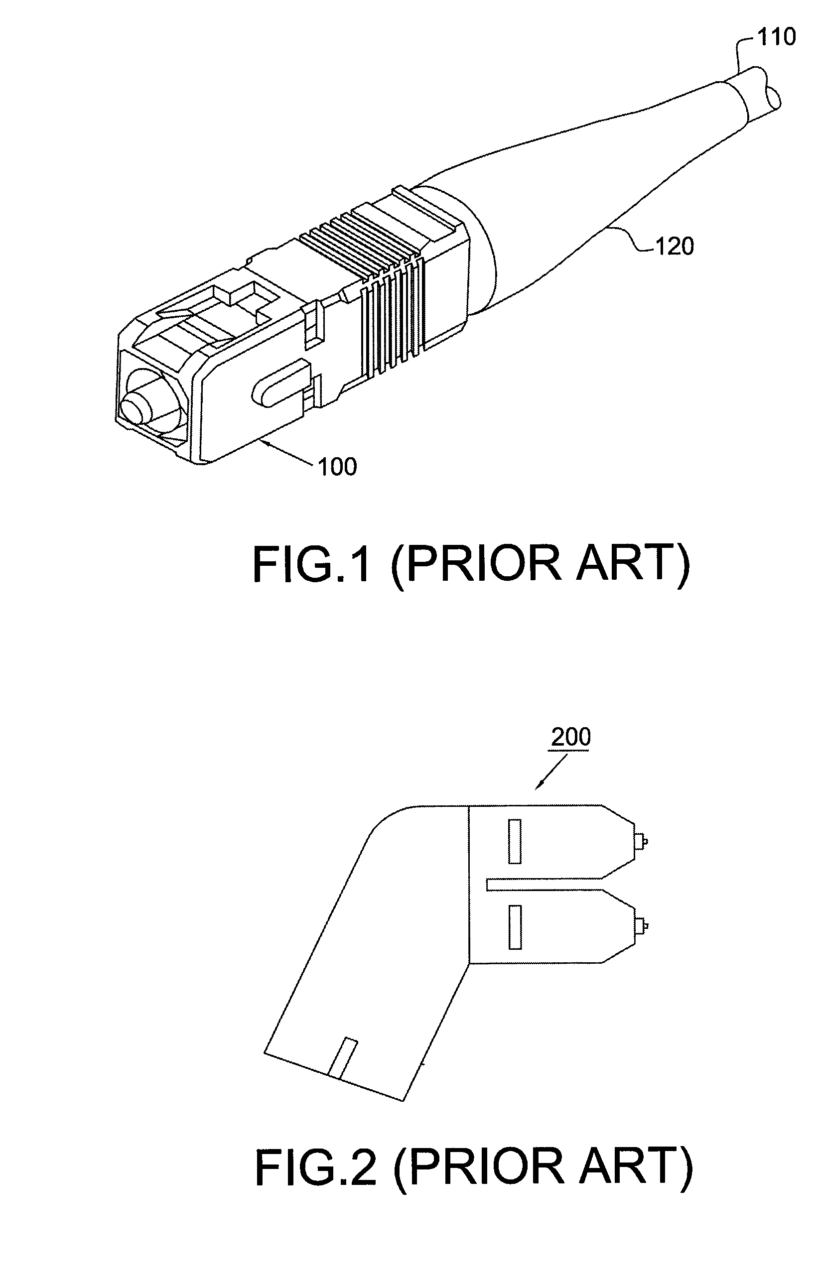
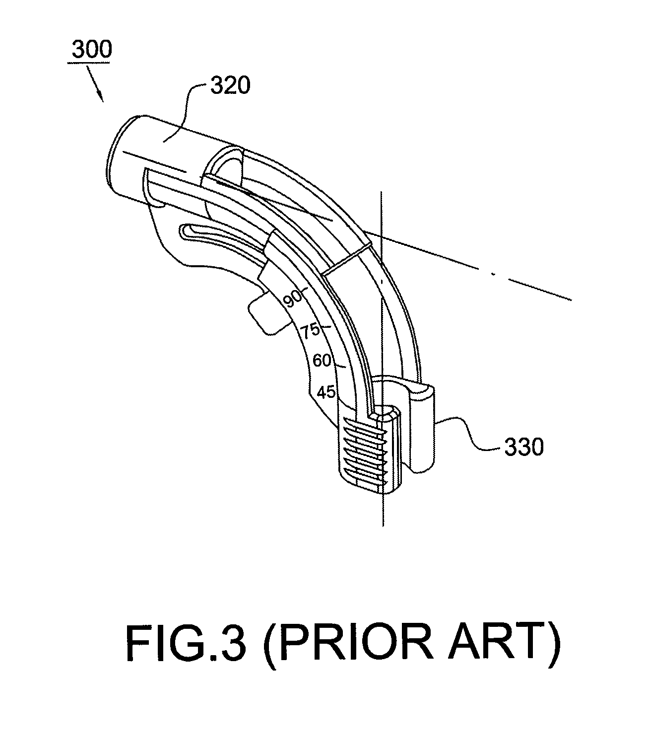
a technology of optical fiber connector and boot, which is applied in the field of optical fiber connector, can solve the problems of difficult angled connector b>200/b>, power loss of optical signal passing through optical fiber, and complicated moving portion mechanism b>330/b>
- Summary
- Abstract
- Description
- Claims
- Application Information
AI Technical Summary
Benefits of technology
Problems solved by technology
Method used
Image

Examples
Embodiment Construction
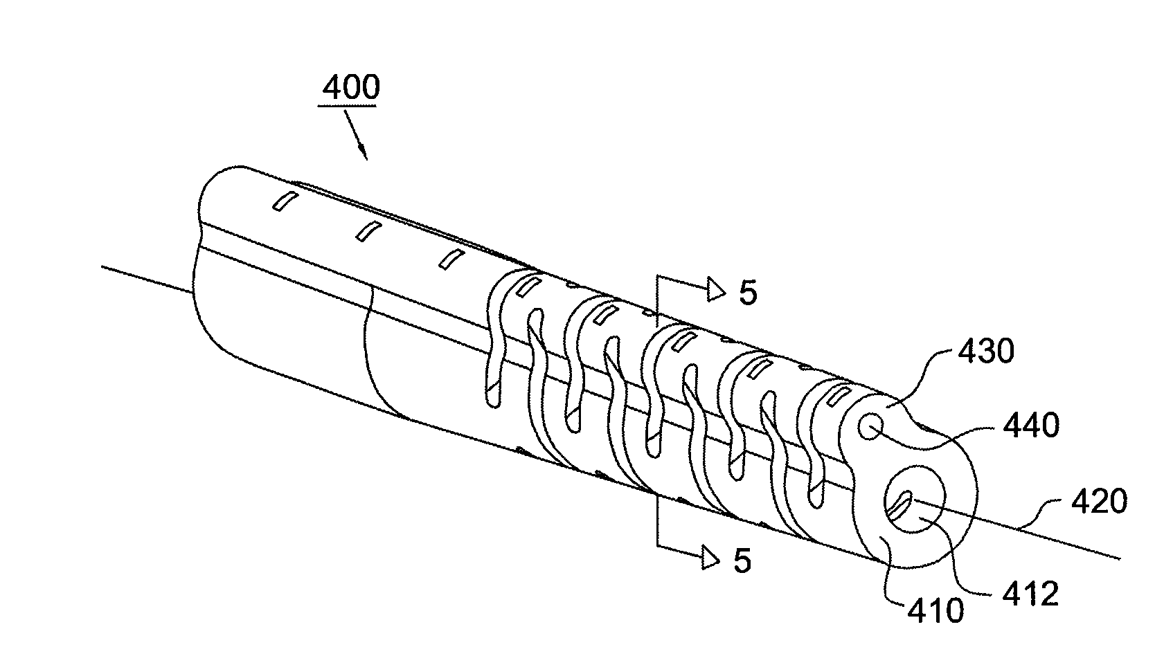
[0020]Referring to FIGS. 4 and 5, the flexibly bended boot 400 of the present invention is for an optical fiber connector. The boot 400 is adjacent to an optical fiber connector and surrounds an optical fiber (not shown in the figures). The boot 400 includes an elastic hollow body 410 which is cylindrical and defines an axial direction 420. A protrusion portion 430 is integrally formed on the outer surface of the body 410 along the axial direction 420. In addition, a member 440 with the property of plasticity is axially embedded in the protrusion portion 430. The member 440 can be integrally formed and is a metal wire, such as an iron wire
[0021]According to the present invention, the boot 400 can be bent to a desired shape in subjection to an external force. When the boot 400 is bent, the member 440 will also be bent accordingly. Since the member 440 has the property of plasticity, the boot 400 can still be kept in the desired shape even though when the external force vanishes. Simi...
PUM
 Abstract
Description
Claims
Application Information