Image Forming Apparatus

a technology of image forming apparatus and cleaning unit, which is applied in the direction of electrographic process apparatus, instruments, optics, etc., can solve the problems of time-consuming and complicated maintenance work, and achieve the effect of reducing the overall size of the image forming apparatus and easy maintenance work for the cleaning uni

Active Publication Date: 2009-08-06
BROTHER KOGYO KK
View PDF10 Cites 30 Cited by
  • Summary
  • Abstract
  • Description
  • Claims
  • Application Information

AI Technical Summary

Benefits of technology

[0012]According to the present invention, the maintenance work for the cleaning unit can be readily performed and the overall size of the image forming apparatus can be reduced.

Problems solved by technology

However, in the above conventional image forming apparatus, because the cleaning unit is arranged below the conveyor belt, it is necessary to remove the conveyor belt during the maintenance of the cleaning unit.
Therefore, the maintenance work becomes complicated and time-consuming.

Method used


Image

  • Image Forming Apparatus
  • Image Forming Apparatus
  • Image Forming Apparatus

Examples


first embodiment

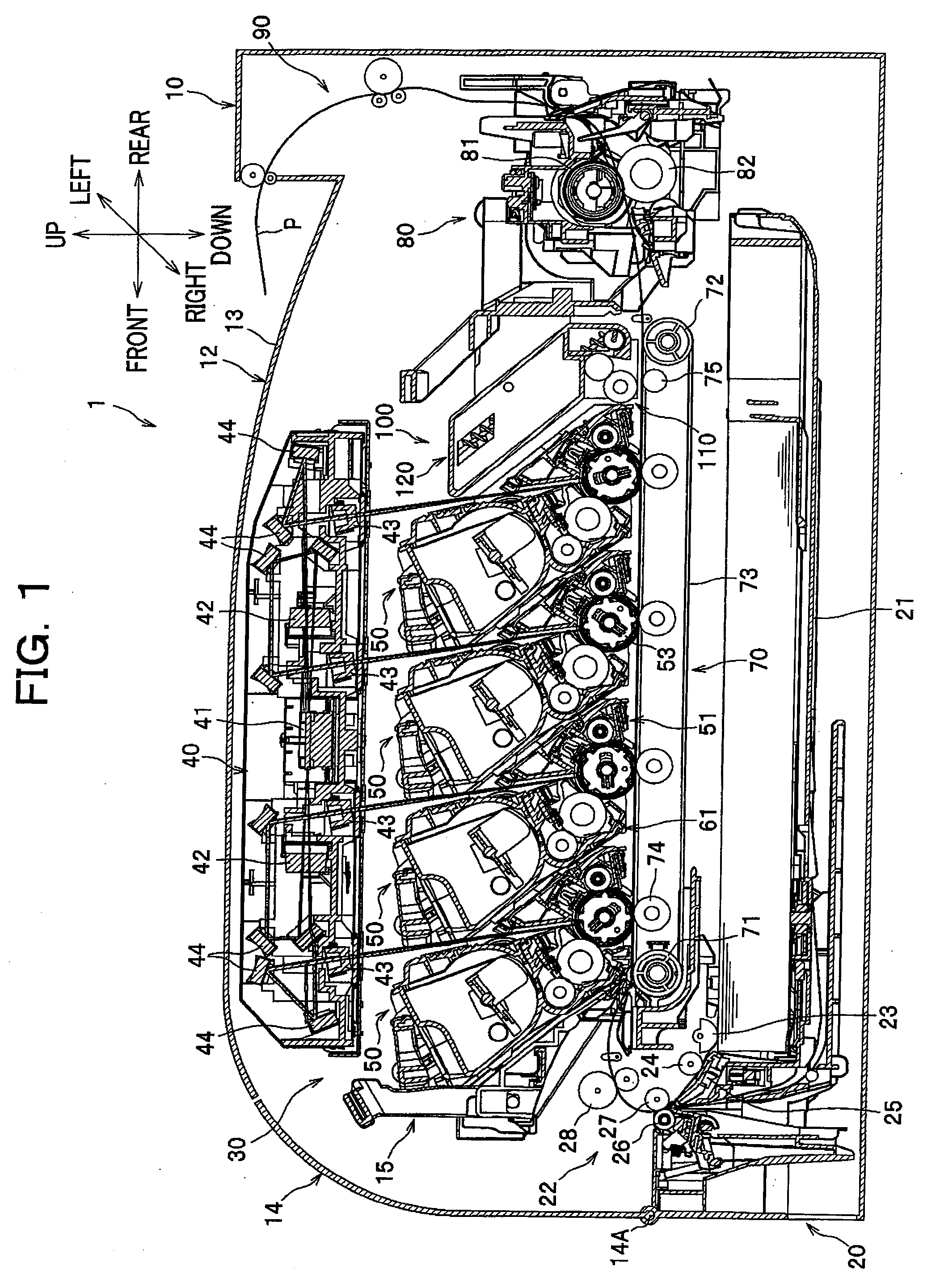
[0029]As seen in FIG. 1, a color printer 1 has a main body 10. A sheet feeding unit 20 configured to feed a sheet of paper P (hereinafter simply referred to as a “sheet” P) as an example of a recording sheet, an image forming device 30 configured to form an image on the sheet P supplied from the sheet feeding unit 20, and a sheet output unit 90 configured to discharge the sheet P having the image thereon from the main body 10 are arranged in the main body 10.

[0030]An upper cover 12 is provided at an upper part of the main body 10. Also, a front cover 14 is provided at a front part of the main body 10. The front cover 14 is pivotally supported on a hinge 14A that is provided at a lower part of the main body 10. The front cover 14 is swung in the front-and-rear direction around the hinge 14A so as to be opened and closed. The upper surface of the upper cover 12 provides a sheet output tray 13 for receiving and stacking sheets P discharged from the main body 10. A scanner unit 40 to be...

second embodiment

[0081]A second embodiment of the present invention will be described with reference to FIG. 8. In the following description, parts different from those employed in the first embodiment will be mainly described, and description of like or similar parts will be omitted or briefly stated.

[0082]A color printer according to the second embodiment is substantially the same as that of the first embodiment. However, as best seen in FIG. 8, of the four process cartridges 50, 50, 50, 200 arranged tandem in the drawer frame 15, the downstream-most process cartridge 200 positioned at the downstream end along the sheet conveyance passage is different from the corresponding process cartridge 50 according to the first embodiment.

[0083]To be more specific, the process cartridge 200 includes a photoconductor cartridge 251, a developing cartridge 261, a cleaner portion 210, and a waste toner box 220. The developing cartridge 261 is integrally formed with the waste toner box 220 through a connecting po...

third embodiment

[0085]A third embodiment of the present invention will be described with reference to FIGS. 9A and 9B.

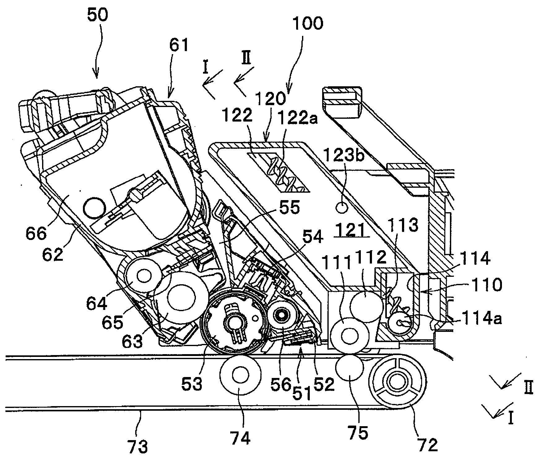
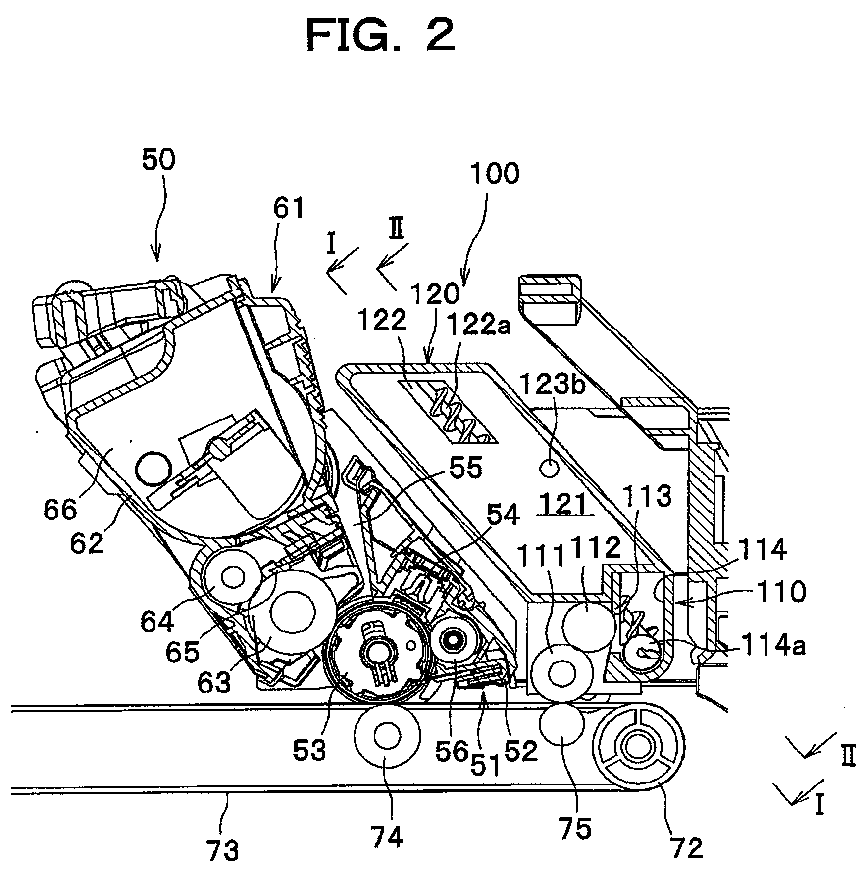
[0086]As best seen in FIG. 9B, a cleaning unit 300 according to the third embodiment is different from the cleaning unit 100 according to the first embodiment in that a cleaner portion 310 and a waste toner box 320 are separable from each other.

[0087]The cleaner portion 310 includes a cleaning roller 311 as a cleaning member, a collecting roller 312, a blade 313, and a carrier unit 314. A first auger 314a is provided inside the carrier unit 314. Further, a rocking member 315 is provided at each side surface of the cleaner portion 310.

[0088]The waste toner box 320 includes a storage portion 321, and a waste toner loading portion 322. A second auger 322a is provided inside the waste toner loading portion 322. As seen FIGS. 9A and 9B, the second auger 322a extends downward beyond the lower end of the waste toner box 320, so that in such a position that the waste toner box 320 is attach...


PUM


Abstract

An image forming apparatus includes: an image forming unit having a plurality of photoconductor drums arranged in tandem; a conveyor belt arranged opposite to the plurality of photoconductor drums and configured to convey a recording sheet; a cleaning unit having a cleaning member positioned in contact with the conveyor belt to collect substance adhering to the conveyor belt, and a receptacle configured to store the substance collected by the cleaning member, wherein the cleaning unit is arranged on the same side as the image forming unit with respect to the conveyor belt; and a positioning member configured to cause the cleaning member to be positioned at a contacting position where the cleaning member contacts with the conveyor belt and at a spaced-apart position where the cleaning member is away from the conveyor belt.

Description

CROSS REFERENCE TO RELATED APPLICATION[0001]This application claims the foreign priority benefit under Title 35, United States Code, §119(a)-(d) of Japanese Patent Application No. 2008-022143 filed on Jan. 31, 2008 in the Japan Patent Office, the disclosure of which is herein incorporated by reference in its entirety.BACKGROUND OF THE INVENTION[0002]The present invention relates to an image forming apparatus such as a color laser printer.[0003]An image forming apparatus such as a laser printer is generally known, which comprises a plurality of development devices each containing different color toner, a plurality of photoconductor drums each of which is supplied with toner from a corresponding development device via a developing roller, a belt arranged opposite to the plurality of photoconductor drums, and a plurality of transfer devices configured to cause toner retained on the plurality of photoconductor drums to be attracted to the belt. In this image forming apparatus, the plura...

Claims


Application Information

Patent Timeline
Patent Type & Authority Applications(United States)
IPC IPC(8): G03G21/20
CPCG03G15/168G03G21/00G03G2215/1661G03G2215/0141
Inventor SAKUMA, SUSUMU
Owner BROTHER KOGYO KK
Why Eureka
Try Eureka