Image Forming Apparatus

a technology of image forming apparatus and forming apparatus, which is applied in the direction of electrographic process apparatus, instruments, optics, etc., can solve the problems of time-consuming and complicated maintenance work, and achieve the effect of reducing the overall size reducing the height of the image forming apparatus, and facilitating maintenance work for the cleaning uni

Inactive Publication Date: 2009-09-10
BROTHER KOGYO KK
View PDF0 Cites 82 Cited by
  • Summary
  • Abstract
  • Description
  • Claims
  • Application Information

AI Technical Summary

Benefits of technology

[0012]According to this image forming apparatus, because the cleaning unit for the intermediate transfer belt is arranged on the same side as the image forming unit with respect to the intermediate transfer belt, the height of the image forming apparatus can be reduced. Further, because the image forming unit and the cleaning unit are supported in the support member which is configured to be pulled out from the main body of the apparatus together with the image forming unit and the cleaning unit, it is possible to remove the cleaning member together with the image forming unit. Therefore, the maintenance of the cleaning unit can be performed without the need for removing the intermediate transfer belt and by the same manner of operations as the image forming unit is attached to or detached from the main body of the apparatus.
[0013]According to the present invention, the maintenance work for the cleaning unit can be readily performed and the overall size of the image forming apparatus can be reduced.

Problems solved by technology

However, an image forming apparatus including a cleaning unit requires maintenance of the cleaning unit in order to dispose of adhering substance that has been removed and collected from the belt.
Therefore, the maintenance work becomes complicated and time-consuming.

Method used


Image

  • Image Forming Apparatus
  • Image Forming Apparatus
  • Image Forming Apparatus

Examples


first embodiment

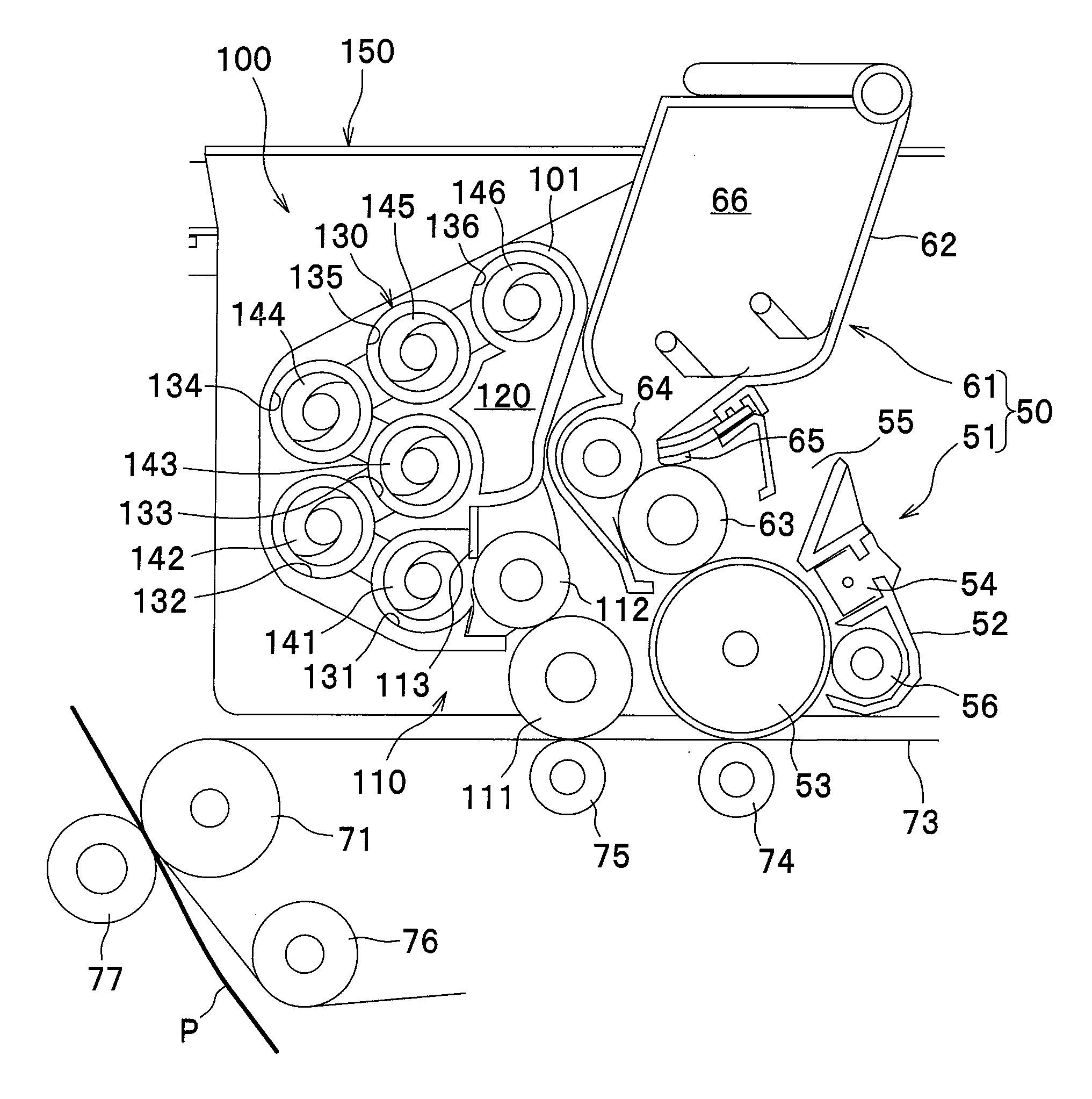
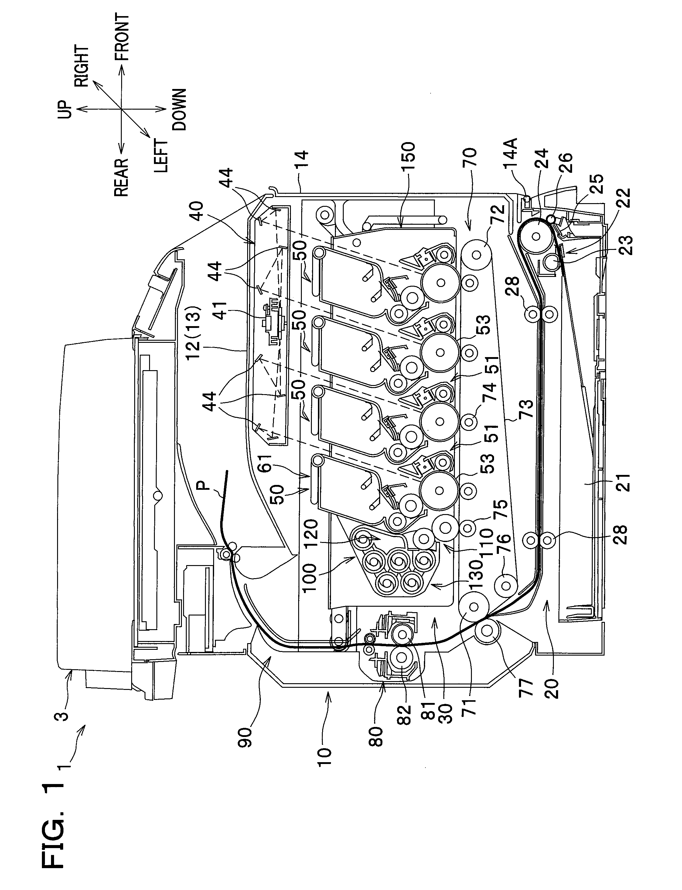
[0029]As seen in FIG. 1, a color printer 1 has a main body 10. The color printer 1 is provided with a sheet feeding unit 20 configured to feed a sheet of paper P (hereinafter simply referred to as a “sheet” P) as an example of a recording sheet, an image forming device 30 configured to form an image on the sheet P supplied from the sheet feeding unit 20, and a sheet output unit 90 configured to discharge the sheet P having the image thereon from the main body 10, which are arranged in the main body 10. The color printer 1 is also provided with a flat-bed scanner 3 at an upper part of the main body 10.

[0030]An upper cover 12 is provided at an upper part of the main body 10. Also, a front cover 14 is provided at a front part of the main body 10. The front cover 14 is pivotally supported on a hinge 14A that is provided at a lower part of the main body 10. The front cover 14 is swung open and closed in the front-and-rear direction around the hinge 14A. The upper surface of the upper cov...

second embodiment

[0092]A second embodiment of the present invention will be described below. In the following description, parts different from those employed in the first embodiment will be mainly described, and like or similar parts will be denoted by the same reference numerals and the same names as those in the first embodiment and description thereof will be omitted or briefly stated.

[0093]In the following description, unless otherwise stated, directions of a color printer refer to the directions as seen from a user facing the color printer during its use. To be more specific, referring to FIG. 6, a left-side direction and a right-side direction of the color printer are referred to as a “front side” and a “rear side”, respectively. Also, a direction away from a viewer of FIG. 6 is referred to as a “left side”, and a direction toward the viewer of FIG. 1 as a “right side”. An upper and lower direction in FIG. 6 is referred to as a “vertical direction” or an “upper and lower direction” as it is.

[...

third embodiment

[0113]With reference to FIG. 8, a color printer 1B according to a third embodiment of the present invention will be described.

[0114]The color printer 1B according to the third embodiment is substantially the same in construction as the color printer 1A according to the second embodiment except for the cleaning unit 300.

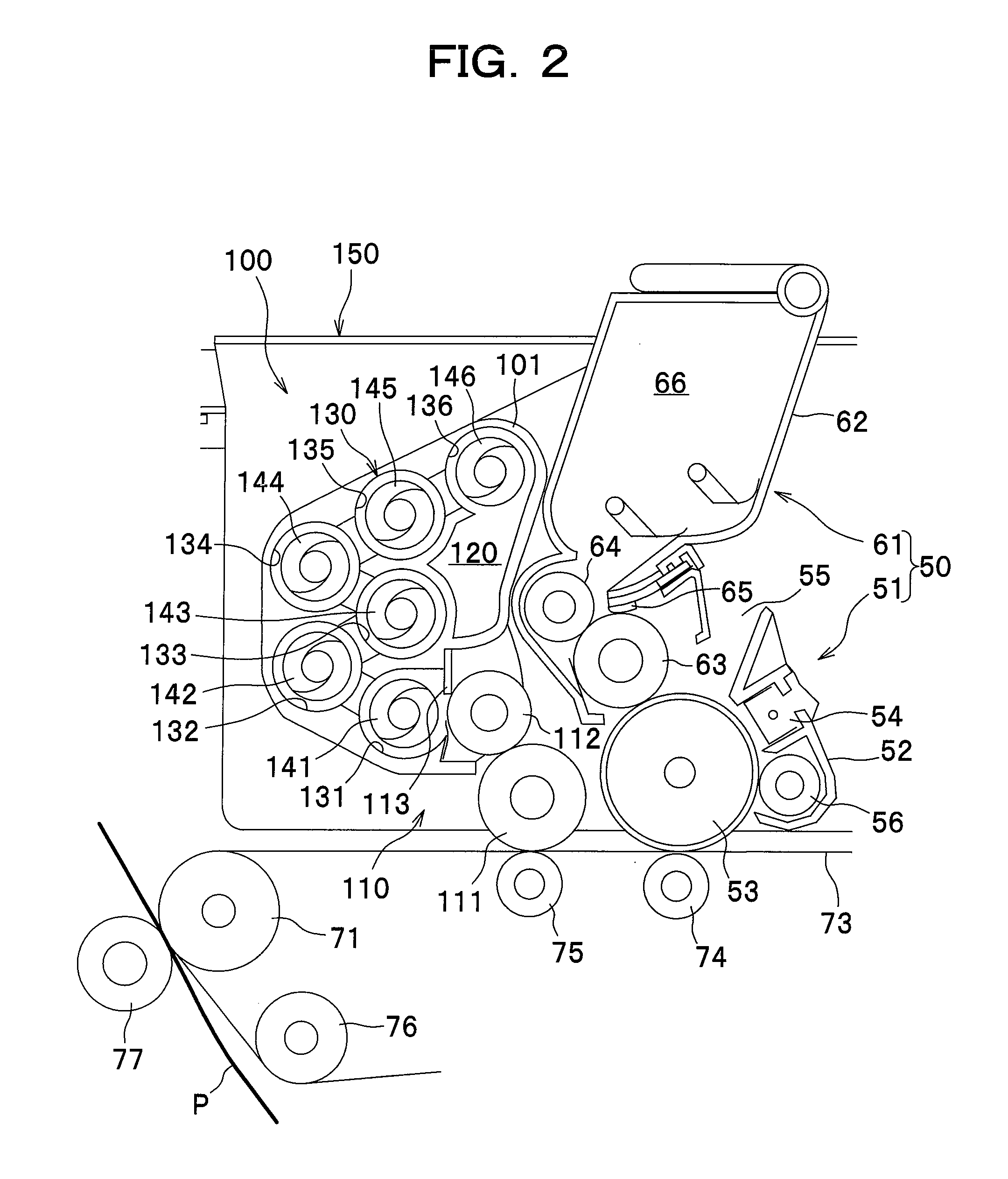
[0115]To be more specific, the cleaning unit 300 includes a cleaning blade 301 which contacts with the intermediate transfer belt 73. The cleaning blade 301 is a thin plate-like elongated member, for example, made of urethane rubber. The cleaning blade 301 extends in the right-and-left directions at the upper end portion of the cleaning unit 300. It is noted that the cleaning unit 300 does not comprise a cleaning roller and a collecting roller unlike the cleaning unit 100 (see FIG. 2) provided with the cleaning roller 111 and the collecting roller 112.

[0116]Because the cleaning blade 301 contacts with the intermediate transfer belt 73, toner T adhering to the intermed...


PUM


Abstract

An image forming apparatus includes: an image forming unit having a plurality of photoconductor drums arranged in tandem; an intermediate transfer belt arranged opposite to the photoconductor drums and configured to receive developer images formed on the photoconductor drums and to transfer the developer images onto a recording sheet; a cleaning unit comprising a cleaning member positioned in contact with the intermediate transfer belt and configured to collect substance adhering to the intermediate transfer belt, and a receptacle configured to store the substance collected by the cleaning member, wherein the cleaning unit is arranged on the same side as the image forming unit with respect to the intermediate transfer belt; and a support member configured to support the image forming unit and the cleaning unit and to be pulled out from a main body.

Description

CROSS REFERENCE TO RELATED APPLICATION[0001]This application claims the foreign priority benefit under Title 35, United States Code, §119(a)-(d) of Japanese Patent Application No. 2008-055542 filed on Mar. 5, 2008 in the Japan Patent Office, the disclosure of which is herein incorporated by reference in its entirety.BACKGROUND OF THE INVENTION[0002]The present invention relates to an image forming apparatus such as a color laser printer, and in particular to an image forming apparatus including an intermediate transfer belt.[0003]An image forming apparatus such as a laser printer is generally known, which comprises a plurality of development devices each containing different color toner, a plurality of photoconductor drums each of which is supplied with toner from a corresponding development device via a developing roller, a conveyor belt arranged opposite to the plurality of photoconductor drums, and a plurality of transfer devices configured to cause toner retained on the pluralit...

Claims


Application Information

Patent Timeline
Patent Type & Authority Applications(United States)
IPC IPC(8): G03G21/10
CPCG03G21/10G03G21/0058G03G2215/0132G03G15/0131G03G15/161G03G21/12G03G15/6529
Inventor SATO, SHOUGOSAKUMA, SUSUMU
Owner BROTHER KOGYO KK
Why Eureka
Try Eureka