Tire and tire rim assembly

a technology of tire rims and flanges, which is applied in the direction of wheel attachments, transportation and packaging, and other domestic objects, can solve the problems of non-pneumatic tires, tire removal is difficult, and the flange typically cannot be flexed over the flang

Inactive Publication Date: 2009-08-27
CHEMTURA CORP
View PDF65 Cites 44 Cited by
  • Summary
  • Abstract
  • Description
  • Claims
  • Application Information

AI Technical Summary

Benefits of technology

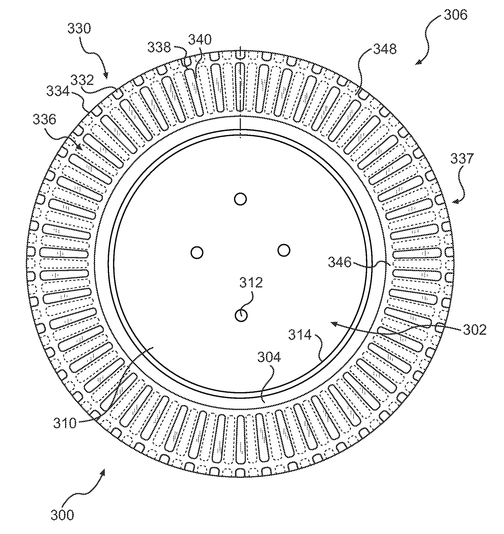
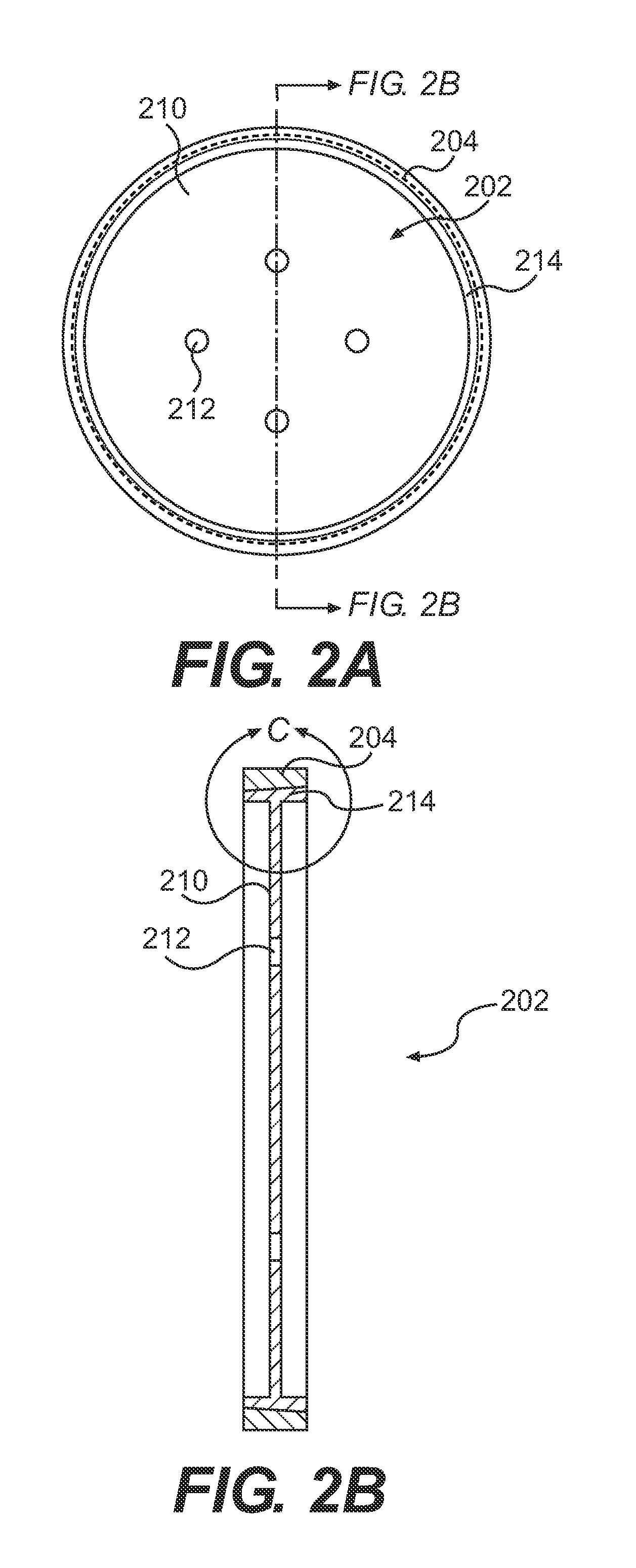
[0007]In a first aspect of the present invention, there is provided a tire rim comprising a central support structure disposed about an axis of rotation, and an outer hoop surrounding the central support structure. The outer hoop comprises a receiving side having a first radial width and a non-receiving side having a second radial width, wherein the first radial width is less than the second radial width to allow a mounting ring disposed on an inner surface of a tire to engage the tire rim laterally from the receiving side.

Problems solved by technology

Non-pneumatic tires, on the other hand, typically cannot be flexed over the flange in a similar fashion, thus making tire removal difficult.
If a conventional non-pneumatic tire is to be removed, the tire must be cut away from the rim, which is time consuming and may damage the tire or rim.
The cutting may also be difficult due to the presence of the flanges.
Due to the difficulties in removing non-pneumatic tires from such rims, conventional damaged tires require the replacement of both the rim and the tire.
Such limitations increase the difficulties to manufacture a tire molded to a rim.
Also, molded tires and their associated rims are cumbersome to handle.

Method used


Image

  • Tire and tire rim assembly
  • Tire and tire rim assembly
  • Tire and tire rim assembly

Examples


Embodiment Construction

[0024]In one embodiment, the present invention relates to a tire rim having an outer hoop for laterally receiving a mounting ring of a tire. The tire rim has a receiving side and a non-receiving side, which are also generally referred to as the outer side and the inner side, respectively. The outer side refers to the side of the rim that faces away from the vehicle to which the rim is mounted and the inner side refers to the side that faces toward the vehicle. The outer side has a radial thickness that is less than the inner side. The mounting ring is slideably engaged on the rim in the lateral direction from the outer side to the inner side. During installation, the mounting ring of a tire moves laterally onto the rim until the receiving side of the mounting ring is flush with the inner side of the rim such that the ring does not extend past the radial plane of the inner side of the rim. Once in place, the tire is removably secured to the rim, for example, with retaining bolts. To ...


PUM


Abstract

A tire rim for a non-pneumatic tire. The tire rim has an outer hoop that slideably engages a mounting ring disposed on the non-pneumatic tire. The mounting ring is slideably engaged in a lateral direction on the outer hoop. The rim and mounting ring can be secured using one or more mounting plates. The rim allows for the non-pneumatic tire to be easily mounted and removed.

Description

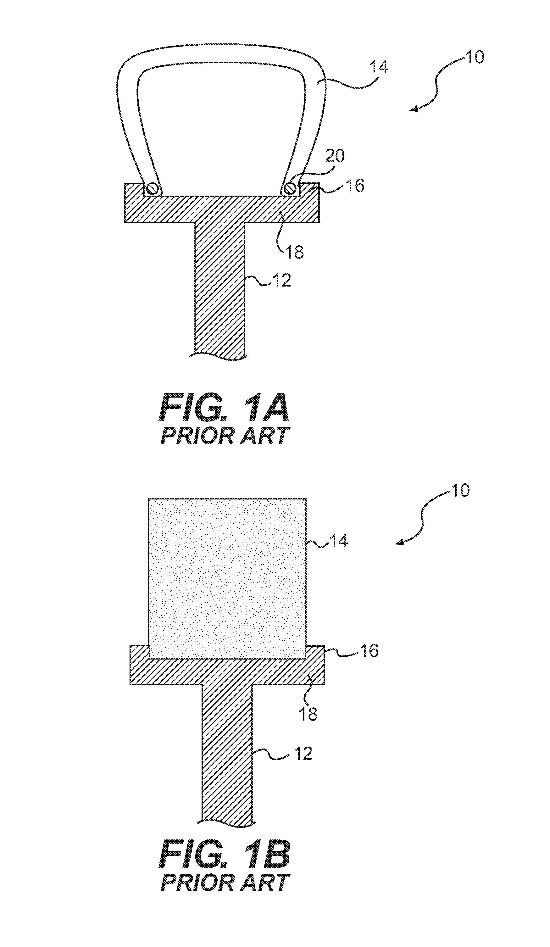
BACKGROUND OF THE INVENTION[0001]1. Field of the Invention[0002]This invention relates to a tire and a tire rim.[0003]2. Discussion of the Background Information[0004]Tire rims provide a connection between tires and the vehicle. Conventional rims 12 have opposing flanges 16 on each side of an outer hoop 18 to secure the tire 14 to the rim 12 as shown in FIGS. 1A and 1B. Inflatable tires 14, such as radial or bias tires, as shown in FIG. 1A, commonly have beads 20 that engage the flange 16 of the rim 12 to form wheel 10. Conventional non-pneumatic tires 14, shown in FIG. 1B, also have flanges 16 and the tire 14 can be directly molded on the rim 12 or adhered to the rim 12. The flanges 16 for non-pneumatic tires 14 provide a structure to assist in molding or adhering the tire 14 to the rim 12. Also, these flanges prevent the lateral movement of the tire with respect to the rim. It would be desirable to be able to replace either the rims or tires without having to replace the entire wh...

Claims


Application Information

Patent Timeline
Patent Type & Authority Applications(United States)
IPC IPC(8): B60C7/24B60C25/00B60B21/00
CPCB60B23/00B60B23/10B29D30/02B60C2007/107B60C7/24B60C7/107
Inventor PALINKAS, RICHARD L.LASKOWITZ, IANNYBAKKEN, GEORGE H.
Owner CHEMTURA CORP
Why Eureka
Try Eureka