
System and method for control of the backing feed for a tufting machine

Inactive Publication Date: 2009-09-03
CARD MONROE
View PDF11 Cites 11 Cited by
  • Summary
  • Abstract
  • Description
  • Claims
  • Application Information

AI Technical Summary

Benefits of technology

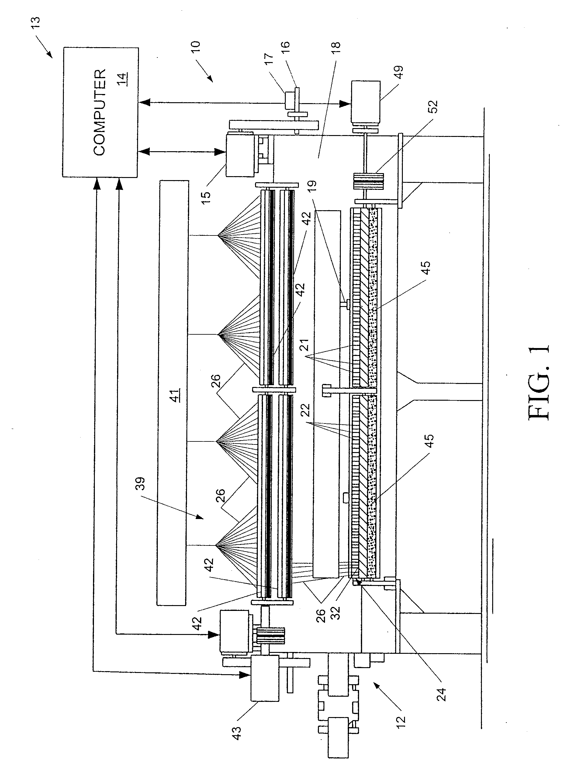
[0008]The yarn feed system will feed a series of yarns to corresponding needles of the tufting machine. The tufting machine can include a single staggered needle bar having two spaced rows of needles separated by a desired stagger, typically ⅛″ to upwards of 1″, although greater or lesser staggers can also be used. However, it will also be understood by those skilled in the art that the tufting machine further could include a pair of needle bars, each carrying a spaced row of needles to which the various yarns are fed by the yarn feed system. Still further, the needle bar or needle bars also can be shiftable needle bars to enable further pattern effects.
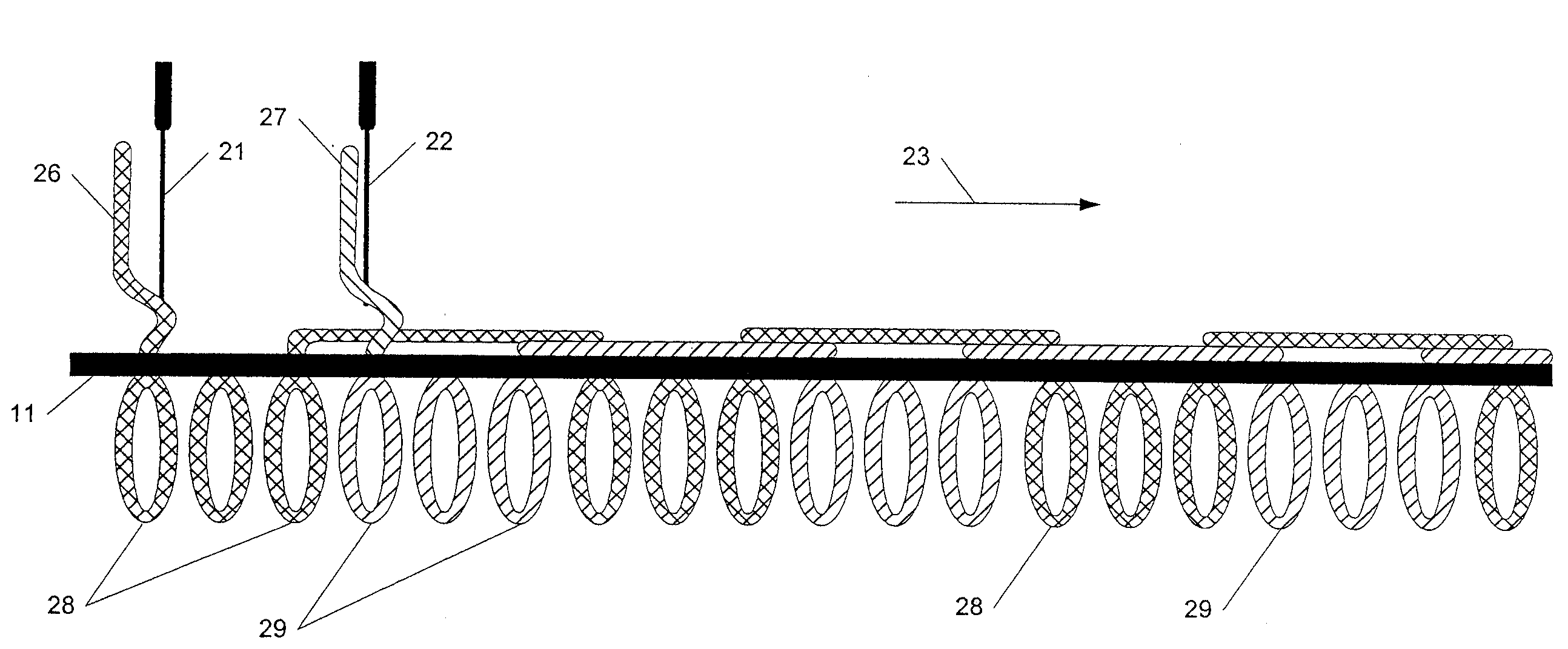
[0012]As a result, the backing feed control system and method of the present invention will enable the formation of two or more consecutive, in line longitudinally extending rows of tufts to be formed across the face of the carpet using the same inline row of needles (i.e., first row of needles) without the yarns from the second or staggered row of needles being intermixed therebetween.

Problems solved by technology

While such patterning systems or devices have enabled an increasing array of different styles and / or pattern effects to be formed in carpets, there is still a limit in the type of patterns or “looks” that can be achieved with such patterning devices.
In addition, pattern attachments such as roll or scroll attachments further can significantly add to the complexity and cost of a tufting machine, while the burying of yarns requires higher pile heights to cover such buried yarns, thus adding further costs to the finished carpet.
Further, tufting machines that utilize the lateral shifting of the primary backing generally have limited production rates or capacities, and typically are used mainly as specialty machines, such as for producing patterned carpets and rugs.
In addition, to provide rugs or carpets with a “woven look” as opposed to a “tufted appearance,” it typically has been necessary to use specialty machinery, such as weaving looms or other dedicated machinery, which can be more costly and labor intensive operate to produce such woven carpets.

Method used


Image

  • System and method for control of the backing feed for a tufting machine
  • System and method for control of the backing feed for a tufting machine
  • System and method for control of the backing feed for a tufting machine

Examples


Embodiment Construction

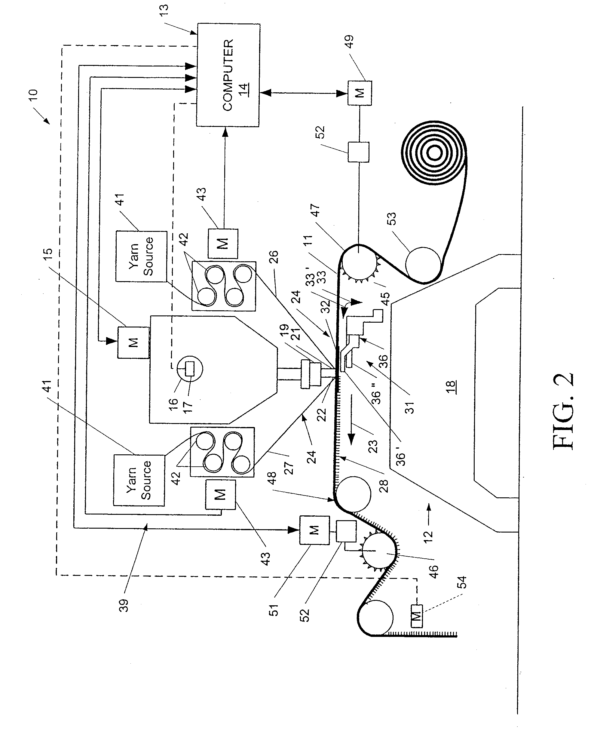
[0019]Referring now in greater detail to the drawings in which like numerals indicate like parts throughout the several views, the present invention is directed to a system 10 and method for controlling the movement of a backing material 11 through a tufting machine 12 in order to produce tufted articles such as carpets that have enhanced pattern effects, such as providing the carpets with a woven look or appearance, as opposed to a traditional tufted appearance, without requiring highly specialized machinery for producing woven carpets or rugs.

[0020]As generally indicated in FIGS. 1 and 2, the backing feed control system 10 can be mounted on or included as part of a computer control system for the tufting machine 12, generally indicated at 13, such as a “Command Performance” tufting machine computer control system manufactured by Card-Monroe Corp. Such a tufting machine control system 13 will include a computer controller or processor 14 that can be programmed with pattern informat...


PUM


Abstract

A method of controlling the feeding of the backing material moving through a tufting machine in order to produce tufted articles such as carpets having a woven look or appearance. The backing material is indexed forwardly along its path of travel through the tufting machine by at least the stitch length for each stitch in a stitch cycle of the programmed pattern. At a desired point in the stitch cycle, the backing material can be indexed forwardly by a greater distance approximately equal to the program stitch length and a calculated jump distance to achieve a desired pattern effect.

Description

CROSS REFERENCE TO RELATED APPLICATIONS[0001]The present patent application is a divisional of co-pending U.S. patent application Ser. No. 11 / 209,053, filed Aug. 22, 2005, which patent application is a formalization of previously filed U.S. Provisional Patent Application Ser. No. 60 / 603,614, filed Aug. 23, 2004, by the inventors named in the present application. This patent application claims the benefit of the filing date of the cited provisional patent application according to the statutes and rules governing provisional patent applications, particularly 35 U.S.C. § 119(e)(1) and 37 CFR § 1.78(a)(4) and (a)(5). The specification and drawings of the provisional patent application as well as those of the co-pending non-provisional application are specifically incorporated herein by reference.FIELD OF THE INVENTION[0002]The present invention generally relates to systems and methods for forming tufted articles, and in particular to a method and system for controlling the advancement o...

Claims


Application Information

Patent Timeline
IPC IPC(8): D05C17/02D05C15/08D05C15/30
CPCD05B19/16D05C17/02D05C15/32Y10T428/23943
Inventor HALL, WILTONCHRISTMAN, JR., WILLIAM M.
Owner CARD MONROE
Learn More