Zipline trolley

a trolley and zipline technology, applied in the direction of railways, rope railways, railways, etc., can solve the problems of difficult to remove and replace wheels, slings, and slings, and difficulty in transporting them from one end of the cable to the other

Inactive Publication Date: 2009-09-10
SKYLINE ZIPLINE GLOBAL
View PDF24 Cites 32 Cited by
  • Summary
  • Abstract
  • Description
  • Claims
  • Application Information

AI Technical Summary

Benefits of technology

[0008]In another aspect of the invention, the side flanges each comprise on

Problems solved by technology

The conventional trolley is bulky and heavy, making it difficult to transport it from one end of the cable to the other.
The design of the trolley also

Method used


Image

  • Zipline trolley
  • Zipline trolley
  • Zipline trolley

Examples


Embodiment Construction

[0015]The present invention comprises a trolley that is lighter and more compact than the conventional trolley. This trolley also allows for the easier removal and replacement of the wheels, lines, and slings.

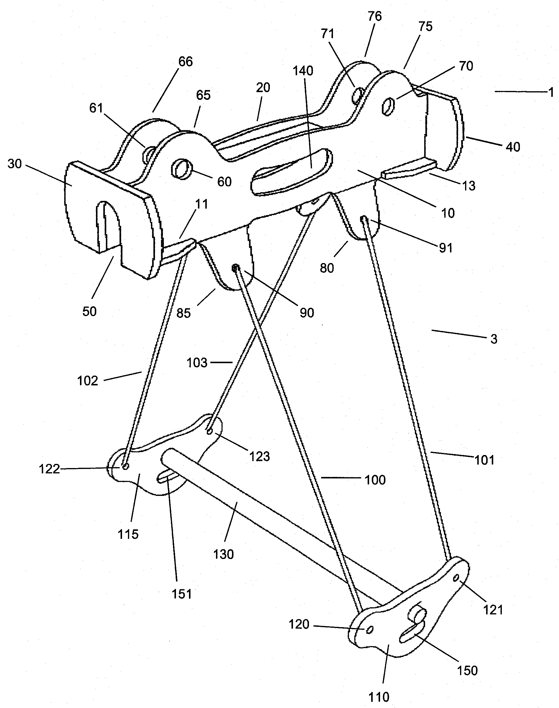
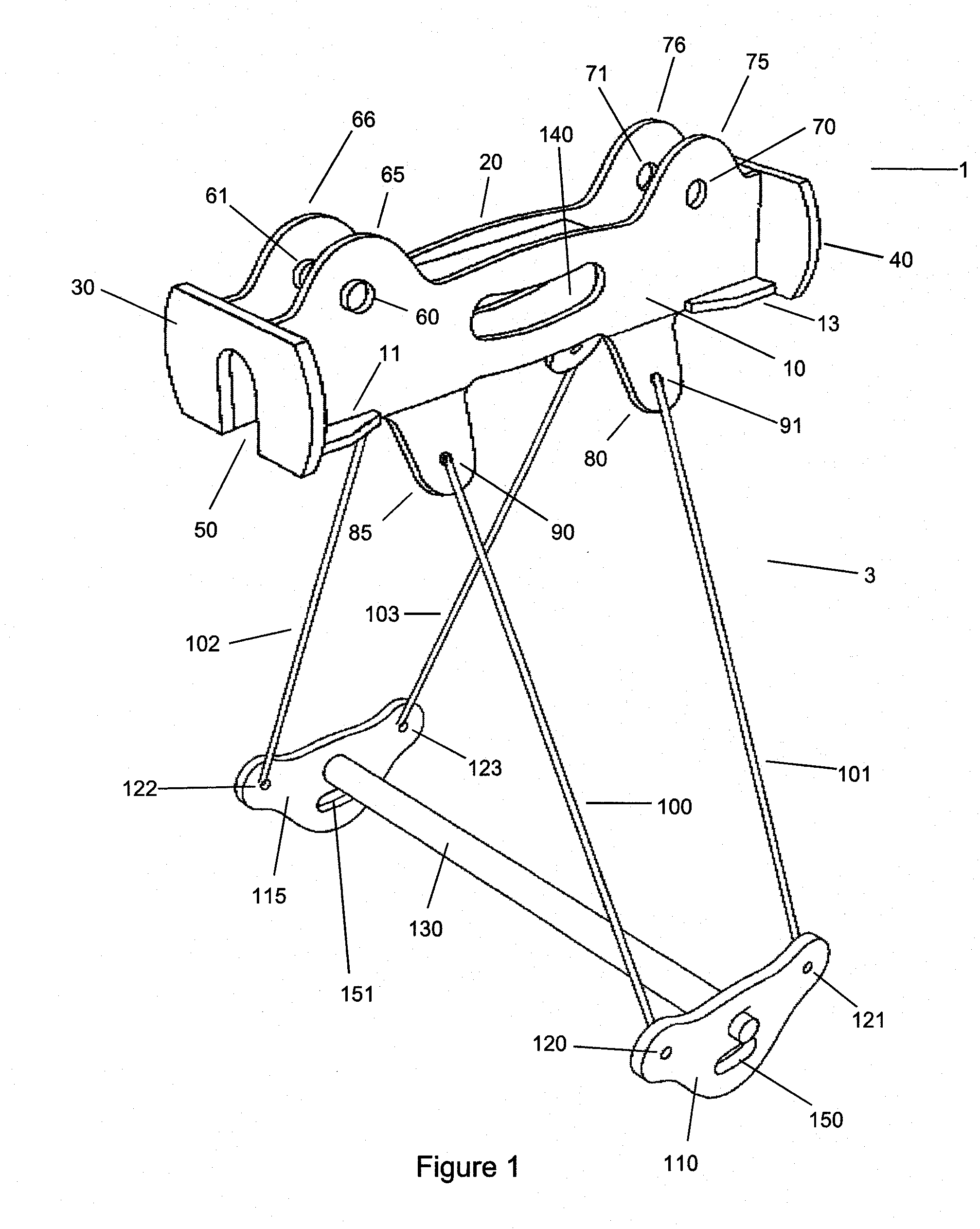
[0016]Referring to FIG. 1, the trolley of the present invention comprises an upper frame 1 with a substantially flat left flange 10 and a substantially flat right flange 20 arranged parallel with each other. The front edge of left flange 10 and the front edge of right flange 20 are rigidly attached to a substantially flat front face 30, while the rear edge of left flange 10 and the rear edge of right flange 20 are rigidly attached to a substantially flat back face 40. Preferably, the front edge of left flange 10 forms a right angle with flat front face 30, and the front edge of right flange 20 forms a right angle with flat front face 30. Similarly, the rear edge of left flange 10 preferably forms a right angle with flat back face 40, and the rear edge of right flange 20 forms a...


PUM


Abstract

The present invention discloses a zipline trolley comprising of two substantially flat side flanges arranged in a parallel configuration, a substantially flat front face attached perpendicularly to the front edges of the side flanges, and a substantially flat back face attached perpendicularly to the rear edges of the side flanges. There are also provided two axles for bearing wheels and four lines for attaching the side flanges to the two spreaders. One set of two lines is attached to the bottom of each of the side flanges. The lines are connected to two spreaders, which are attached to the ends of a handlebar.

Description

CROSS-REFERENCE TO RELATED APPLICATIONS[0001]This application claims the benefit of U.S. Provisional Application No. 60 / 975,942, filed Sep. 28, 2007, the contents of which are hereby incorporated by reference.FIELD OF THE INVENTION[0002]The present invention relates to zipline trolleys.BACKGROUND OF THE INVENTION[0003]Zipline systems typically comprise a trolley that rolls along a suspended length of cable. A conventional trolley is constructed from a cylindrical aluminum frame enclosing two wheels. These wheels roll along the top of the cable. A handlebar is suspended from the bottom of the aluminum frame by four lines. One or more slings may also be used to attach the trolley to the user. The front of the trolley comprises a pair of vertical rings extending away from the trolley. The rings are used to engage the braking mechanism at the end of the cable length.[0004]The conventional trolley is bulky and heavy, making it difficult to transport it from one end of the cable to the ot...

Claims


Application Information

Patent Timeline
IPC IPC(8): B61B7/00
CPCB61B7/00A63G21/22
Inventor SMITH, KEVIN GEOFFREY
Owner SKYLINE ZIPLINE GLOBAL
Why Eureka
Try Eureka