Communication System Using Passive Optical Network and Passive Optical Network

US20090232498A1Inactive Publication Date: 2009-09-17HITACHI LTD

Image

  • Communication System Using Passive Optical Network and Passive Optical Network
  • Communication System Using Passive Optical Network and Passive Optical Network
  • Communication System Using Passive Optical Network and Passive Optical Network

Examples


Embodiment Construction

[0053]A construction and the operation of a communication system using a PON of the invention will be described in detail hereinbelow with reference to the drawings. Although an example in which a GE-PON which has been standardized by the IEEE standard 802.3ah is used as a PON of the invention will be described hereinbelow, the invention can be also embodied by applying another PON such as a GPON or the like which has been standardized by the ITU-T standard G.983.

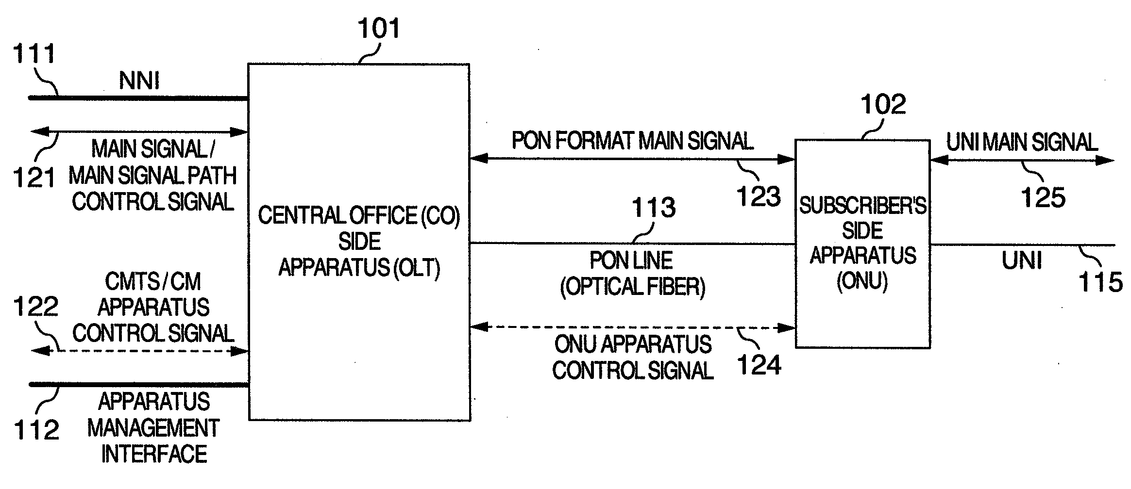
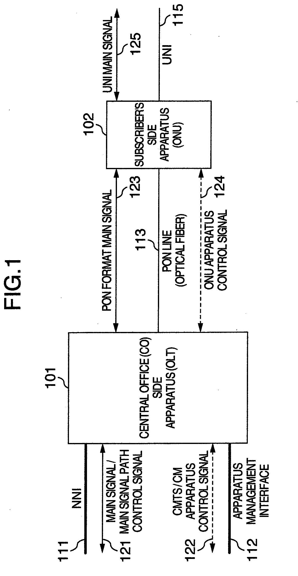
[0054]FIG. 1 is an explanatory diagram showing an example of a construction of apparatuses of the PON and a communication interface and a construction of signals which are transmitted and received.

[0055]The PON of the invention is constructed by an OLT 101 as a station side apparatus and an ONU 102 as a subscriber's side apparatus. In an interval between the OLT 101 and the ONU 102 (PON interval), they are connected by a PON line 113. Generally, a physical media of the PON line 113 is an optical fiber. Although a constructi...


PUM


Abstract

An OLT transmits and receives a CMTS / CM apparatus control signal through an apparatus physical management interface which is physically identical to or different fro a main signal interface (NNI) and processes the CMTS apparatus control signal by itself. When connection of a new ONU is detected by an ONU apparatus control signal, an IP address is allocated by using the CM apparatus control signal in a manner similar to the CM. The CM apparatus control signal regarding the ONU is transmitted and received by using the IP address and a mutual conversion is performed between the CM apparatus control signal and the ONU apparatus control signal. The ONU processes the ONU apparatus control signal in a manner similar to the ONU based on an ordinary PON standard.

Description

INCORPORATION BY REFERENCE[0001]The present application claims priority from Japanese applications JP2007-269647 filed on Oct. 17, 2007 and JP2008-263388 filed on Oct. 17, 2008, the content of which is hereby incorporated by reference into this application.CROSS-REFERENCE TO RELATED APPLICATION[0002]This application is a continuation-in-part of copending U.S. application Ser. No. 12 / 147616, filed Jun. 27, 2008, the disclosure of which is hereby incorporated by reference.BACKGROUND OF THE INVENTION[0003]1. Field of the Invention[0004]The invention relates to a communication system which is constructed by an optical fiber line, an optical splitter, and apparatuses arranged at both ends thereof, which enables transmission and reception of a data packet between the apparatuses at both ends, and which enables one of the apparatuses to make management and setting of the other apparatus, wherein a passive optical network (hereinbelow, abbreviated to PON) is used as a network constructed by...

Claims


Application Information

Patent Timeline
17 Sep 2009
Publication
US20090232498A1
IPC
H04J14/00
CPC
H04J3/0667; H04L41/0213; H04L41/0226; H04Q2011/0088; H04Q11/0067; H04Q2011/0079; H04L41/0896
Inventors
TSUGE, MUNETOSHI; MORI, TAKASHI