
Balancing structure for a single curved tube coriolis flow meter

a flow meter and balancing structure technology, applied in the field of flow meters, can solve the problems of material clogging at the split point inside the manifold, the flow meter at the connecting point to the piping system is impacted, and the flow meter cannot be positioned properly

Active Publication Date: 2009-10-08
MICRO MOTION INC
View PDF10 Cites 7 Cited by
  • Summary
  • Abstract
  • Description
  • Claims
  • Application Information

AI Technical Summary

Benefits of technology

[0017]the torsion member having a center section and where the first end and the second end of the torsion member is configured to vibrate in-phase with the single flow tube and the center section is configured to vibrate in the opposite phase with respect to the single flow tube thereby causing the torsion member to deform in torsion along a torsional vibration axis.
[0025]Preferably, a dongle attached to the torsion member where the dongle is perpendicular to the torsion member and extends downward from the torsion member, away from the single flow tube, and is aligned with the axis of symmetry of the single flow tube and where the dongle is configured to eliminate any residual motion in the first and second manifolds.
[0039]Preferably, the method further comprises a dongle is attached to the torsion member opposite the counterbalance structure and configured to eliminate any residual motion in the two manifolds.
[0053]the torsion member having a center section and where the first end and the second end of the torsion member are configured to vibrate in-phase with the single flow tube and the center section is configured to vibrate in the opposite phase with respect to the single flow tube thereby causing the torsion member to deform in torsion along a torsional vibration axis.
[0061]Preferably, the method further comprises attaching a dongle to the torsion member where the dongle is perpendicular to the torsion member and extends downward from the torsion member, away from the balance member, and is aligned in the plane of the single flow tube and where the dongle is configured to eliminate any residual motion in the first and second manifolds.

Problems solved by technology

One of the problems addressed has been the vibration of the flow meter at the connecting point to the piping system.
Splitting a wide range of different materials into two equal flows is a difficult task for a dual tube design.
In addition, material can become clogged at the split point inside the manifold.
Unfortunately, when the density of the material changes or a different material with a different density is measured, the flow meter is typically no longer in balance.

Method used


Image

  • Balancing structure for a single curved tube coriolis flow meter
  • Balancing structure for a single curved tube coriolis flow meter
  • Balancing structure for a single curved tube coriolis flow meter

Examples


Embodiment Construction

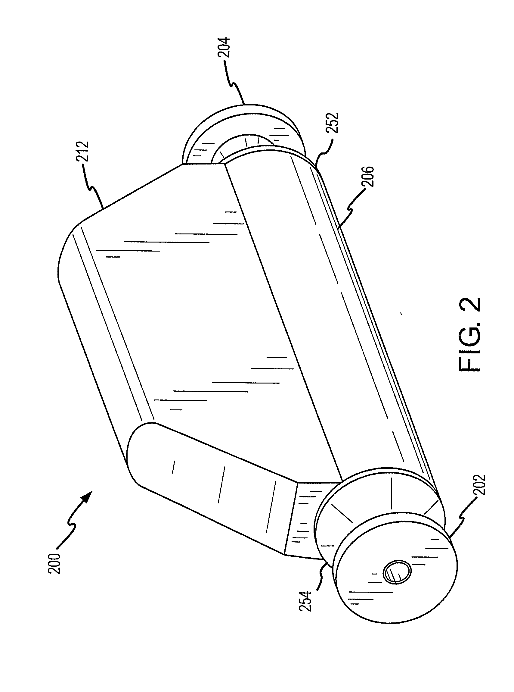
[0080]FIGS. 1-7 and the following description depict specific examples to teach those skilled in the art how to make and use the best mode of the invention. For the purpose of teaching inventive principles, some conventional aspects have been simplified or omitted. Those skilled in the art will appreciate variations from these examples that fall within the scope of the invention. Those skilled in the art will appreciate that the features described below can be combined in various ways to form multiple variations of the invention. As a result, the invention is not limited to the specific examples described below, but only by the claims and their equivalents.

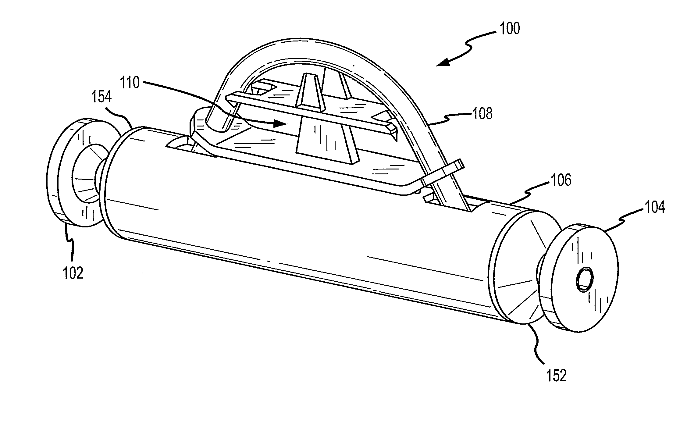
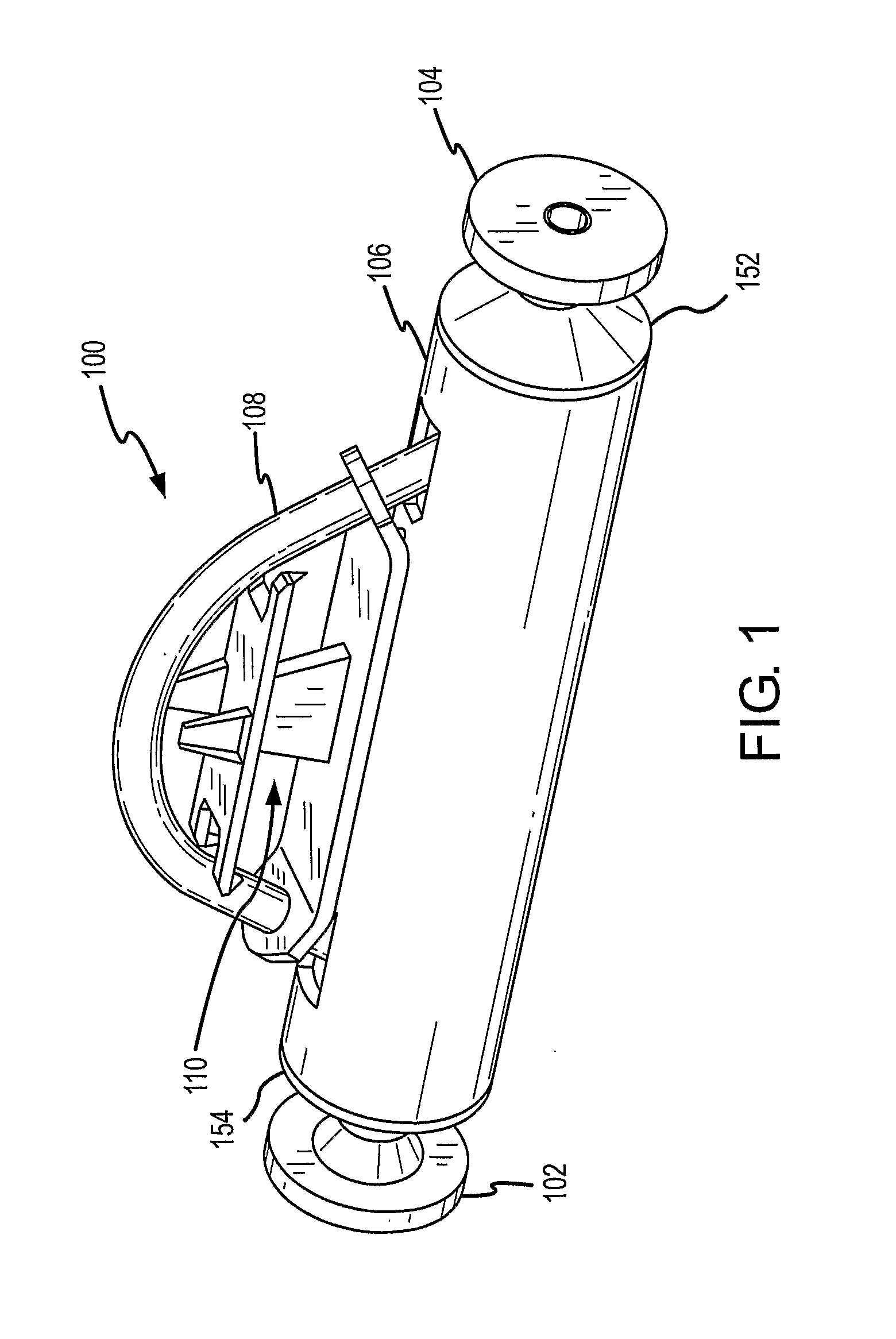
[0081]FIG. 1 is an isometric view of Coriolis flow meter 100 in an example embodiment of the current invention. Coriolis flow meter 100 comprises an inlet flange 102, an outlet flange 104, an inlet manifold 154, an outlet manifold 152, a manifold spacer 106, a single curved flow tube 108 and a balancing structure 110. The inlet an...


PUM

PropertyMeasurementUnit
Lengthaaaaaaaaaa
Densityaaaaaaaaaa
Flexibilityaaaaaaaaaa

Abstract

A Coriolis flow meter is disclosed that uses the deflection of a torsion member (430) to balance the vibration of a single curved flow tube (308). The two ends of the torsion member are attached to, and vibrate with, a center section of the single flow tube (308). A balance member (432) is attached to a center section of the torsion member (430) and vibrates in the opposite phase of the single flow tube (308) causing the torsion member (430) to be deflected in torsion.

Description

BACKGROUND OF THE INVENTION[0001]1. Field of the Invention[0002]The invention is related to the field of flow meters, and in particular, to Coriolis flow meters.[0003]2. Description of the Prior Art[0004]Coriolis flow meters typically operate by vibrating one or more flow tubes and measuring deflections, or phase differences, in the vibrating flow tubes induced by the Coriolis forces from a material flowing through the flow tubes. Coriolis flow meters have a number of different flow tube designs. Some meters have straight flow tubes and some have curved flow tubes. Some meters have a single flow tube and some have two flow tubes. Each type of Coriolis flow meter has been developed to address different problems in the operation of the flow meter. One of the problems addressed has been the vibration of the flow meter at the connecting point to the piping system. Typically the flow meter will have a flange at each end of the meter to allow the meter to be coupled into the piping system...

Claims


Application Information

Patent Timeline
IPC IPC(8): G01F1/84B23P11/00
CPCG01F1/8409G01F1/8413Y10T29/49826G01F1/8472G01F1/8418G01F1/84G01F1/00
Inventor VAN CLEVE, CRAIG BRAINERD
Owner MICRO MOTION INC
Learn More