Progressive Crimping Method

Active Publication Date: 2009-10-15
PANDUIT
View PDF48 Cites 13 Cited by
  • Summary
  • Abstract
  • Description
  • Claims
  • Application Information

AI Technical Summary

Problems solved by technology

However, assembling the compression connector 10 for crimping is difficult because prior to crimping, the wires 19 are not retained in the compression connector 10.

Method used


Image

  • Progressive Crimping Method
  • Progressive Crimping Method
  • Progressive Crimping Method

Examples


Embodiment Construction

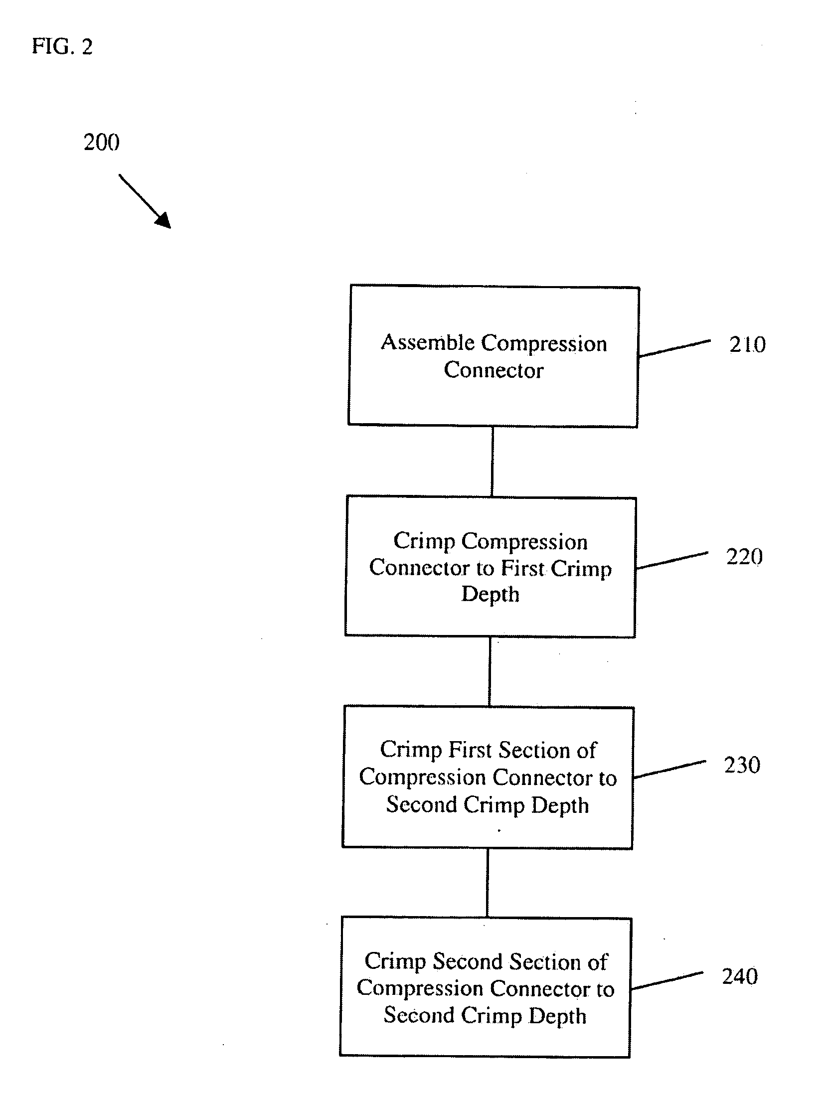
[0032]FIG. 2 is a flow chart of a method 200 for progressively crimping a compression connector 20 according to an embodiment of the present invention. The method 200 includes the following steps, which are described in more detail below. At step 210, a compression connector 20 is assembled. At step 220, the compression connector 20 is crimped to a first crimp depth CD1. At step 230, a first section 22 of the compression connector 20 is crimped to a second crimp depth CD2. At step 240, a, second section 24 of the compression connector 20 is crimped to the second crimp depth CD2. The method 200 is described with reference to the progressive crimping system 2000 of FIGS. 10-21, but it is understood that other implementations are possible.

[0033]At step 210, the compression connector 20, such as a PANDUIT® HTCT H-Tap Compression Connector, is prepared or assembled for crimping, as described in U.S. Pat. No. 6,818,830 and U.S. Pat. No. 7,121,001, each of which is hereby incorporated by r...


PUM

PropertyMeasurementUnit
Depthaaaaaaaaaa

Abstract

Certain embodiments of the present invention provide a progressive crimping method. The method includes assembling a compression connector for crimping, the compression connector including a first section and a second section; crimping the compression connector to a first crimp depth; crimping the first section of the compression connector to a second crimp depth; and crimping the second section of the compression connector to the second crimp depth.

Description

BACKGROUND OF THE INVENTION[0001]The present invention relates to compression connectors. More particularly, the present invention relates to systems and methods for progressively crimping compression connectors.[0002]FIG. 1 is a flow chart of a method 100 for crimping a compression connector 10 according to the prior art. The method 100 includes the following steps, which are described in more detail below.. At step 110, a compression connector 10 is assembled. At step 120, a first section 12 of the compression connector 10 is crimped to a crimp depth CD. At step 130, a second section 14 of the compression connector 10 is crimped to the crimp depth CD. At step 140, the third section 16 of the compression connector 10 is crimped to the crimp depth CD. The prior art crimping method 100 is described with reference to: the prior art crimping system 1000 of FIGS. 3-9.[0003]At step 110 the compression connector 10 such as a BURNDY® TYPE YGHP Compression Connector or a BURNDY® YGRP Compre...

Claims


Application Information

Patent Timeline
IPC IPC(8): H01R43/048H01R43/04H01R43/058B21D31/00B21D7/06B21D37/10
CPCH01R4/186H01R9/03Y10T29/53235Y10T29/49181Y10T29/53996H01R43/048
Inventor SOKOL, ROBERT L.
Owner PANDUIT
Why Eureka
Try Eureka