Traction and Stability Control System and Method for a Vehicle with Mechanically Independent Front and Rear Traction Wheels

a technology of traction control system and rear traction wheel, which is applied in the direction of brake system, tractors, instruments, etc., can solve the problems of wasting energy, degrading acceleration performance of the vehicle, and powertrains that cannot independently request the powertrain, so as to avoid wheel slippage, improve vehicle stability, and avoid loss of lateral tractive effort.

Active Publication Date: 2009-10-15
FORD GLOBAL TECH LLC
View PDF15 Cites 74 Cited by
  • Summary
  • Abstract
  • Description
  • Claims
  • Application Information

AI Technical Summary

Benefits of technology

[0013]According to a still further feature of the invention, each traction wheel is provided with a friction brake for retarding traction wheel speed under the control of a brake control module thereby avoiding wheel slip.
[0014]The invention can improve vehicle stability during coast down conditions when the deceleration torque for one set of traction wheels causes more wheel deceleration than surface conditions can accommodate. Slip

Problems solved by technology

A vehicle chassis dynamics control system for such hybrid electric vehicle powertrains cannot independently request the powertrain to adjust (increase or decrease) driving torque for one set of traction wheels and to separately adjust torque for the other set of traction wheels.
Application of friction braking to a traction wheel that has minimal traction will oppose torque distribution to one set of traction wheels thereby wasting energy an

Method used


Image

  • Traction and Stability Control System and Method for a Vehicle with Mechanically Independent Front and Rear Traction Wheels
  • Traction and Stability Control System and Method for a Vehicle with Mechanically Independent Front and Rear Traction Wheels
  • Traction and Stability Control System and Method for a Vehicle with Mechanically Independent Front and Rear Traction Wheels

Examples


Embodiment Construction

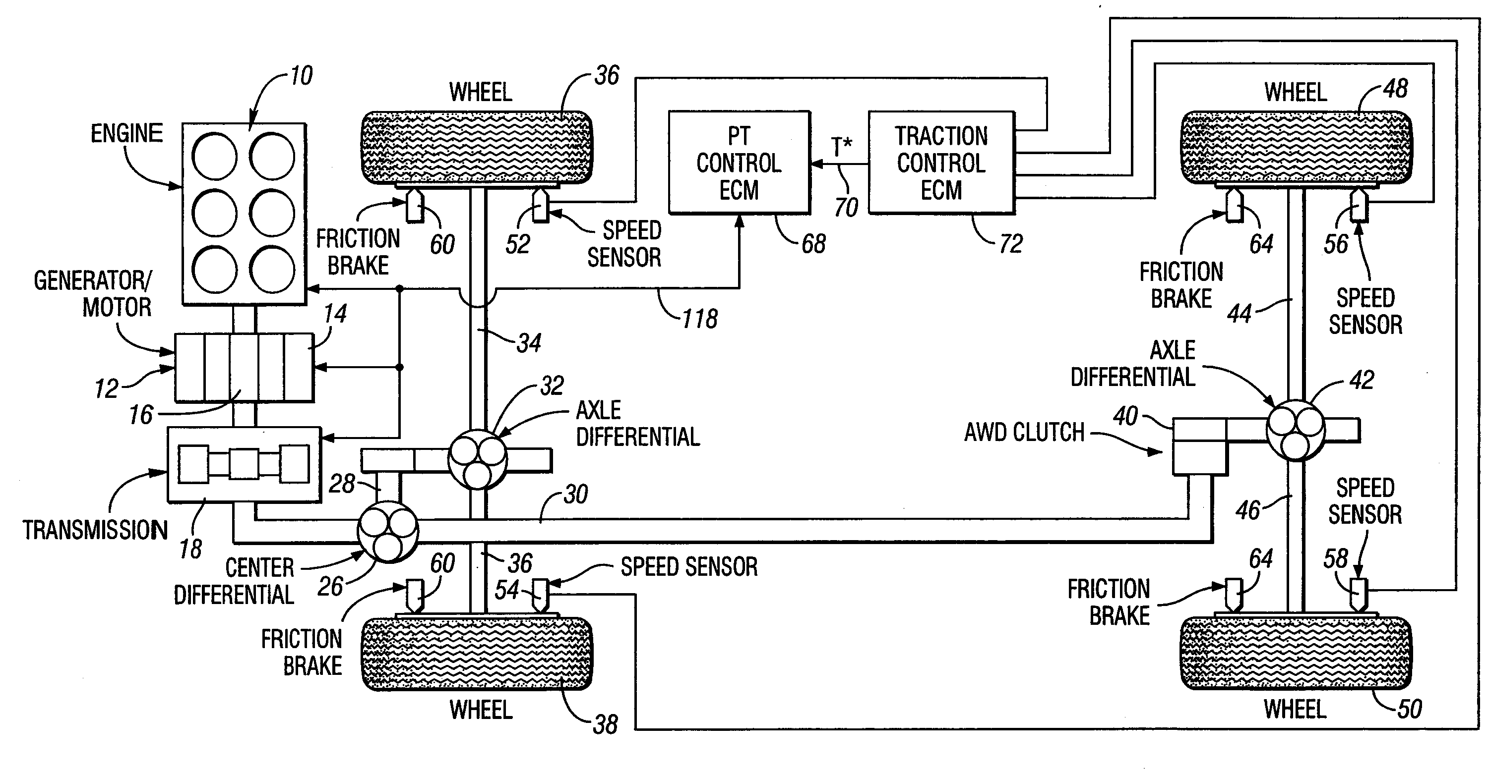
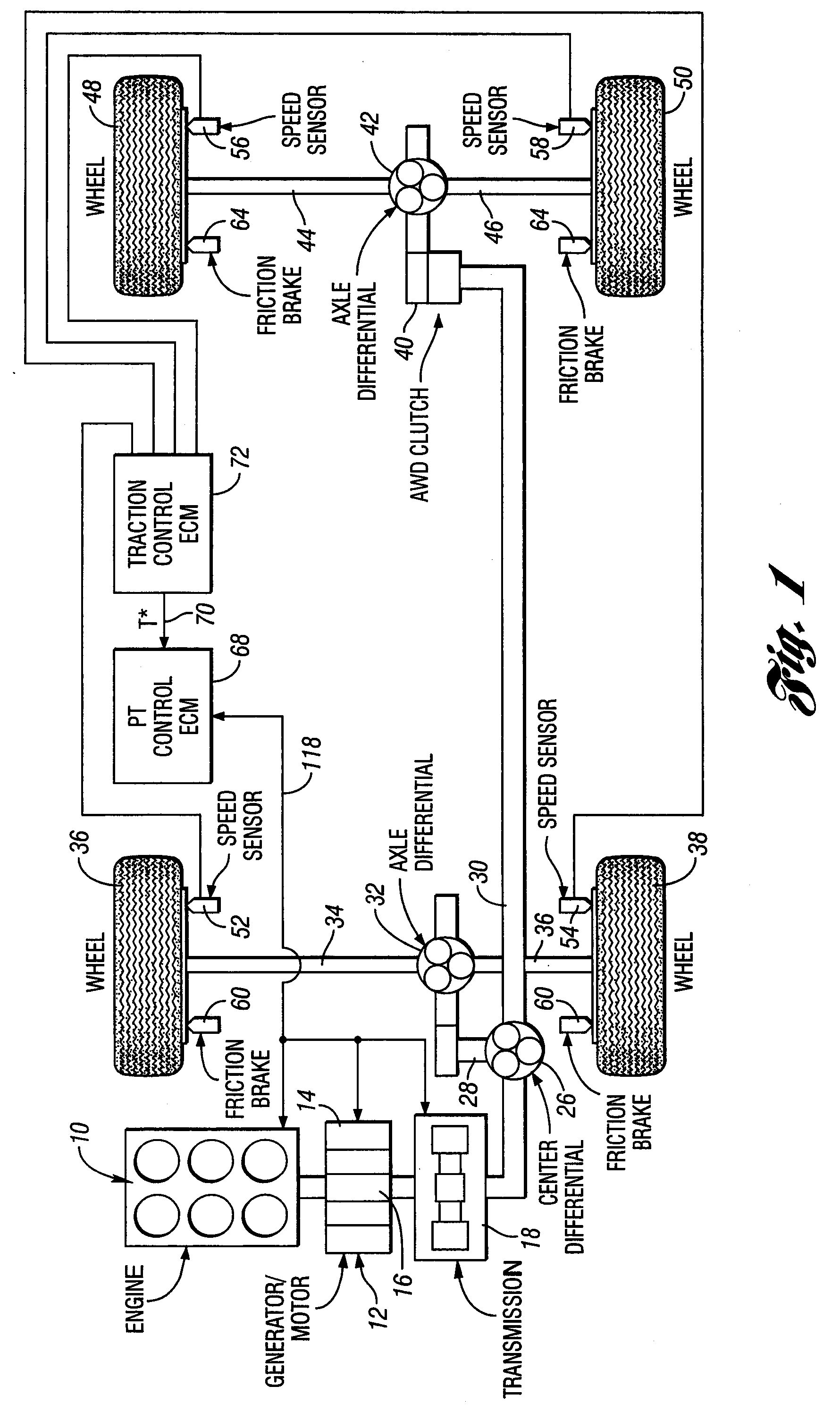
[0022]FIG. 1 schematically illustrates an all-wheel drive hybrid electric vehicle powertrain with an engine shown at 10 and a generator-motor shown at 12. The engine and the generator-motor are a source of motive power. The engine 10 includes a torque output crankshaft drivably connected to a rotor of the generator-motor.

[0023]When the generator-motor is in a torque delivery mode, electric power is distributed to generator-motor windings schematically, shown at 14, so that the rotor torque schematically, shown at 16, augments engine power distributed to a geared transmission schematically shown at 18.

[0024]The torque output shaft of the transmission 18 is delivered to a center axle differential 20. Typically, the differential 20 would include a differential carrier connected drivably to the power output shaft of the transmission. The carrier is part of an assembly that includes pinions that drivably engage a differential side gear, one side gear being connected by gearing 28 to one ...


PUM


Abstract

A vehicle powertrain with mechanically independent sets of front and rear traction wheels has separate motive power units. An electronic control system including traction wheel slip control is electronically coupled to a first motive power unit and to a second motive power unit to separately establish maximum rear wheel traction and maximum front wheel traction. Independent requests are made for an increase or a decrease in wheel torque for one set of traction wheels and an increase or decrease in wheel torque for the other set of traction wheels thereby improving acceleration performance and enhancing vehicle stability.

Description

BACKGROUND OF THE INVENTION[0001]1. Field of the Invention[0002]The invention relates to a powertrain for a hybrid electric vehicle with front and rear driving axles that are mechanically independent.[0003]2. Background Art[0004]It is known design practice for a hybrid electric vehicle powertrain to use traction controlled systems and stability control systems for the vehicle. These separate systems usually are interfaced in a powertrain assembly that cannot independently control each driving axle. More recent design concepts for hybrid electric vehicle powertrains use a mechanically independent electric motor drive for one of the axles as the other axle is powered by an internal combustion engine. Examples of hybrid electric vehicle powertrains with that configuration are disclosed in U.S. patent publications US 2002 / 0041167 and US 2005 / 0178592. A vehicle chassis dynamics control system for such hybrid electric vehicle powertrains cannot independently request the powertrain to adju...

Claims


Application Information

Patent Timeline
IPC IPC(8): B60K28/16G06F19/00B60L50/10
CPCB60K6/365Y02T10/642B60K6/485B60K6/52B60K6/547B60K17/356B60K28/16B60L2240/423B60T8/175B60T8/1769B60T2270/202B60W10/06B60W10/08B60W10/119B60W20/00B60W30/18172B60W2520/26B60W2520/28B60W2540/10B60W2540/12B60W2710/0666B60W2710/083B60W2720/403Y02T10/6226Y02T10/6234Y02T10/6265Y02T10/6286B60K6/442Y02T10/62Y02T10/64B60K17/3462B60W20/40
Inventor BOESCH, MATHEW ALAN
Owner FORD GLOBAL TECH LLC
Why Eureka
Try Eureka