Eureka AIR delivers breakthrough ideas for toughest innovation challenges, trusted by R&D personnel around the world.

Method for improving the driving stability of a vehicle

a technology for improving the driving stability and vehicle, applied in the direction of steering initiation, instruments, vessel construction, etc., can solve the problem of greater risk of slipping when negotiating curves, and achieve the effect of improving the driving stability of the vehicl

Inactive Publication Date: 2011-10-27
ROBERT BOSCH GMBH
View PDF3 Cites 23 Cited by
  • Summary
  • Abstract
  • Description
  • Claims
  • Application Information

AI Technical Summary

Benefits of technology

[0004]An object of the present invention is to improve the driving stability of a vehicle via automatic interventions of an active steering system and / or a braking device.
[0005]The example method according to the present invention for improving the driving stability may be used in vehicles which are equipped in advance with an activatable braking device and with an active steering system, the braking device being automatically adjustable, via control signals, for example of a driver assistance system, and the active steering system being automatically adjustable in such a way that the vehicle follows a desired trajectory even without any intervention by the driver. The active steering system is, in particular, a steering system having a superimposed steering gear which allows an additional steering angle to be superimposed on the steering angle predefined by the driver. The superimposed steering angle may be set by activating an actuator in the superimposed steering gear.
[0008]In the example method according to the present invention for improving the driving stability it is provided that a trajectory is ascertained in a situation-specific manner on the basis of the lane and / or obstacle detection, whereupon the active steering system and / or the braking device are set in such a way that at least one transverse dynamic vehicle state variable does not exceed an associated limiting value. The transverse dynamic state variable is, for example, the vehicle transverse acceleration or the yaw rate. This procedure makes it possible either to negotiate a curve without an obstacle or to perform an avoidance maneuver around an obstacle with the highest possible driving stability. The obstacle may be another vehicle, which is to be driven around or passed, for which a simple or double lane change is necessary. Stationary or quasi-stationary obstacles, such as, for example, people, may also be considered.
[0010]An embodiment is basically possible in which the vehicle speed is initially reduced before automatic steering occurs.
[0013]In particular, the height of the instantaneous center of gravity in the vehicle has a significant effect on the driving stability. The higher the position of the center of gravity, the greater is the risk of tipping over when negotiating curves, which is to be taken account in particular in the case of utility vehicles. By parametrizing the active steering system and / or the braking device, the increased risk of tipping over may be taken into account, for example by reducing the limiting values, in particular in view of the transverse dynamic driving state variables. Accordingly, for example, the vehicle speed is reduced more by operating the braking device, compared to low positions of the center of gravity.
[0014]Additionally or alternatively to influencing the parametrization of the active steering system and / or braking device, the position of the center of gravity may also be taken into account when selecting the trajectory. In this case, a trajectory having a suitable radius may be selected as a function of the vertical position of the center of gravity, trajectories having greater radii being advantageous for reducing the risk of tipping over as the height of the position of the center of gravity increases.

Problems solved by technology

The higher the position of the center of gravity, the greater is the risk of tipping over when negotiating curves, which is to be taken account in particular in the case of utility vehicles.

Method used


Image

  • Method for improving the driving stability of a vehicle
  • Method for improving the driving stability of a vehicle
  • Method for improving the driving stability of a vehicle

Examples


Embodiment Construction

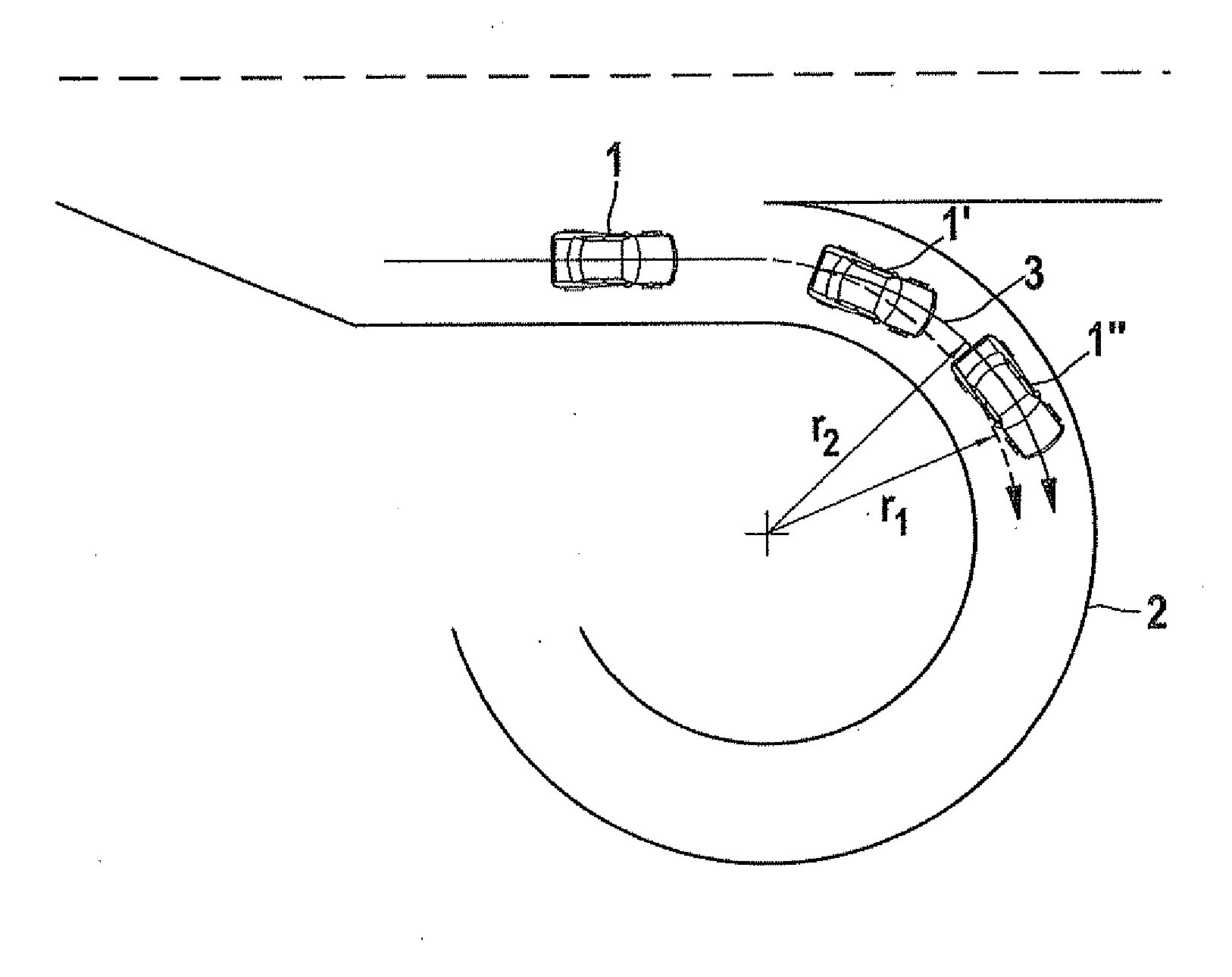
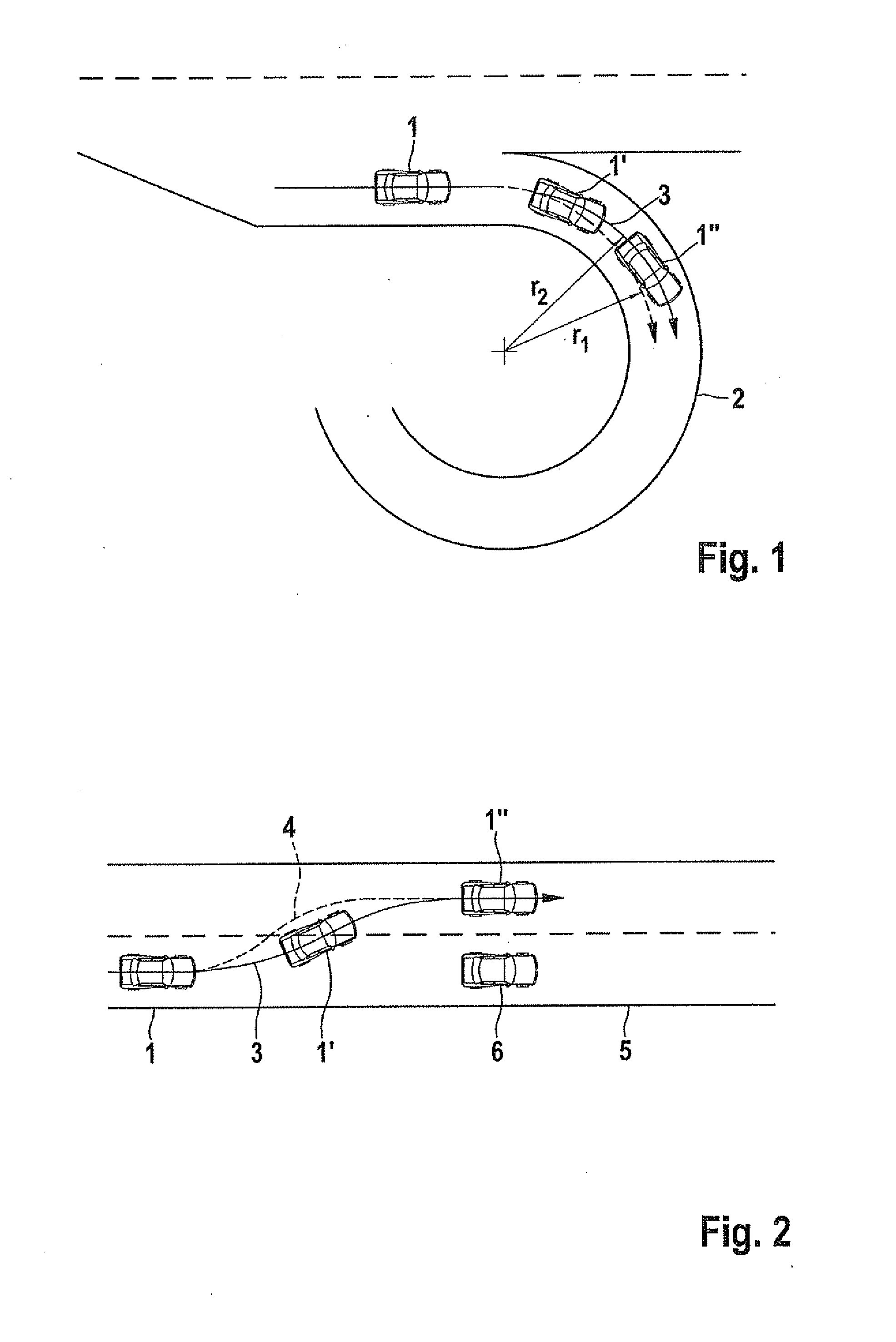
[0021]FIG. 1 shows a vehicle 1 when entering a curved roadway 2. Vehicle 1 is illustrated in different positions at the beginning and within the curve, the more advanced positions of the vehicle in the curve being identified as 1′ and 1″. Different trajectories 3 and 4 are marked in curved roadway 2, vehicle 1 following first trajectory 3 having the greater curve radius r2, drawn using a solid line. On the other hand, second trajectory 4, which is drawn using a dashed line, has a smaller radius r1. Both trajectories 3, 4, move within curved roadway 2. Due to the greater radius r2 on trajectory 3, vehicle 1, which follows this trajectory 3, is subject to lower vehicle transverse accelerations.

[0022]FIG. 2 shows a driving situation on straight roadway 5. Vehicle 1 performs a lane change to drive around a preceding other vehicle 6. Similarly to the exemplary embodiment of FIG. 1, two trajectories 3 (solid line) and 4 (dashed line) are marked of which the vehicle follows the first traje...


PUM


Abstract

A method for improving the driving stability of a vehicle, including ascertaining a trajectory to be followed by the vehicle in a situation-specific manner, an active steering system and / or a braking device being set in the vehicle in such a way that at least one transverse dynamic state variable is within an associated limiting value.

Description

CROSS REFERENCE[0001]The present application claims the benefit under 35 U.S.C. §119of German Patent Application No. DE 102010028109.3, filed on Apr. 22, 2010, which expressly incorporated herein by reference in its entirety.FIELD OF THE INVENTION[0002]The present invention relates to a method for improving the driving stability of a vehicle.BACKGROUND INFORMATION[0003]German Patent Application No. DE 195 06 364 C2 describes a vehicle control system in which the instantaneous position of a vehicle and the trajectory to a destination is determined with the aid of a navigation device. The vehicle velocity and a steering system for controlling the steering angle are set in such a way that the vehicle is able to reliably negotiate a curve.SUMMARY[0004]An object of the present invention is to improve the driving stability of a vehicle via automatic interventions of an active steering system and / or a braking device.[0005]The example method according to the present invention for improving ...

Claims


Application Information

Patent Timeline
Patent Type & Authority Applications(United States)
IPC IPC(8): G06F7/00B60T8/1755B62D6/00B60W10/18B60W30/02B60W30/09
CPCB60W10/18B60W10/20B60W2720/125B60W30/09B60W2530/10B60W30/02
Inventor BRUEGGEMANN, RAINERREIZE, ANDREASFRUEH, PHILIPP
Owner ROBERT BOSCH GMBH
Why Eureka
Eureka Blog
Learn More