Multi-cartridge cutting tool and railway wheel boring assembly

a cutting tool and multi-cartridge technology, applied in the direction of cutting inserts, manufacturing tools, shaping cutters, etc., can solve the problems of deficient feed rate and cutting insert life in some machining applications

Active Publication Date: 2009-10-15
KENNAMETAL INC +1
View PDF12 Cites 12 Cited by
  • Summary
  • Abstract
  • Description
  • Claims
  • Application Information

AI Technical Summary

Problems solved by technology

However, it has been observed with cutting tools having four round cutting inserts that the feed rates and the life of the cutting inserts are deficient for some machining applications and some particular materials to be machined.

Method used


Image

  • Multi-cartridge cutting tool and railway wheel boring assembly
  • Multi-cartridge cutting tool and railway wheel boring assembly
  • Multi-cartridge cutting tool and railway wheel boring assembly

Examples


Embodiment Construction

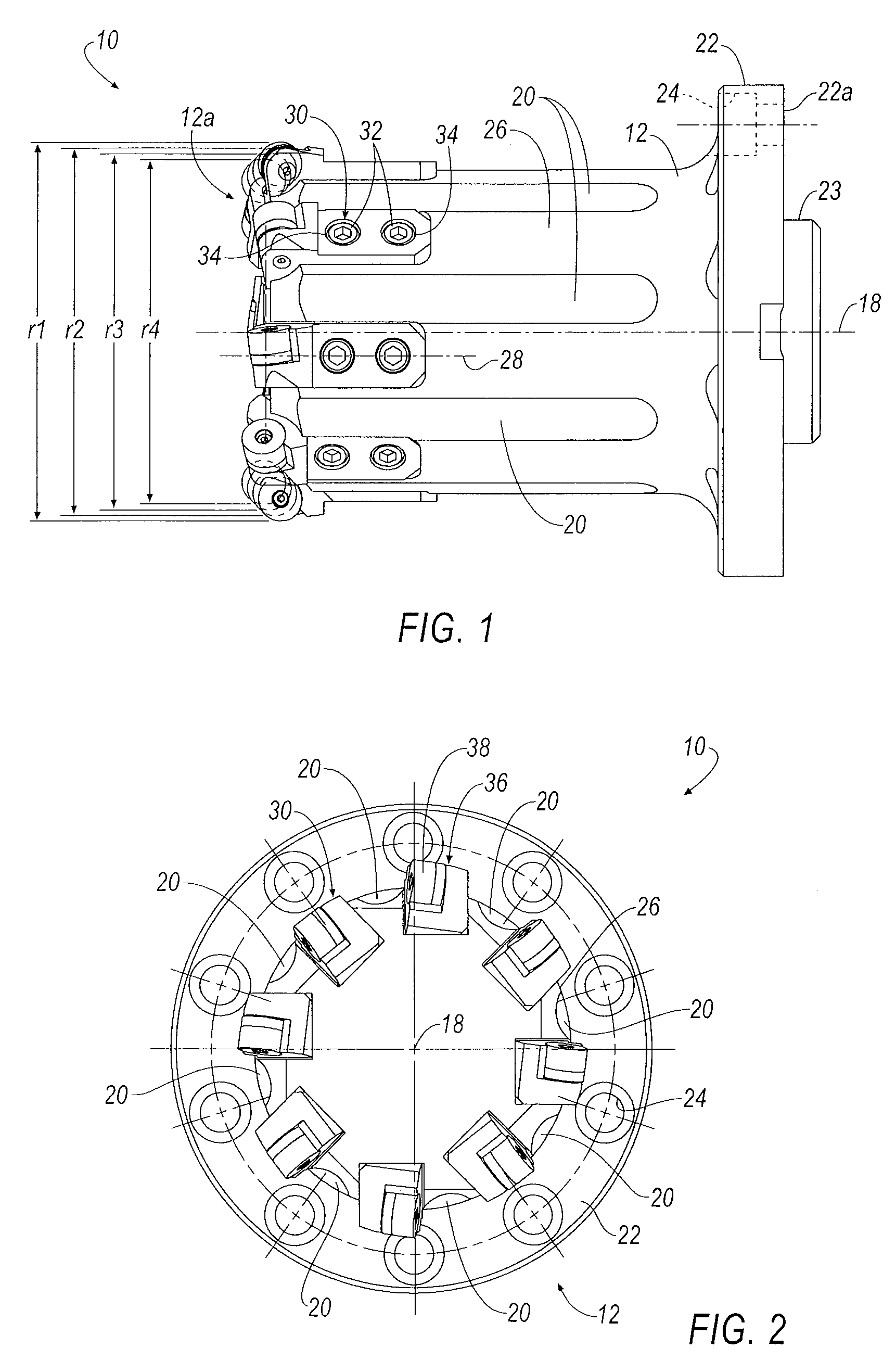
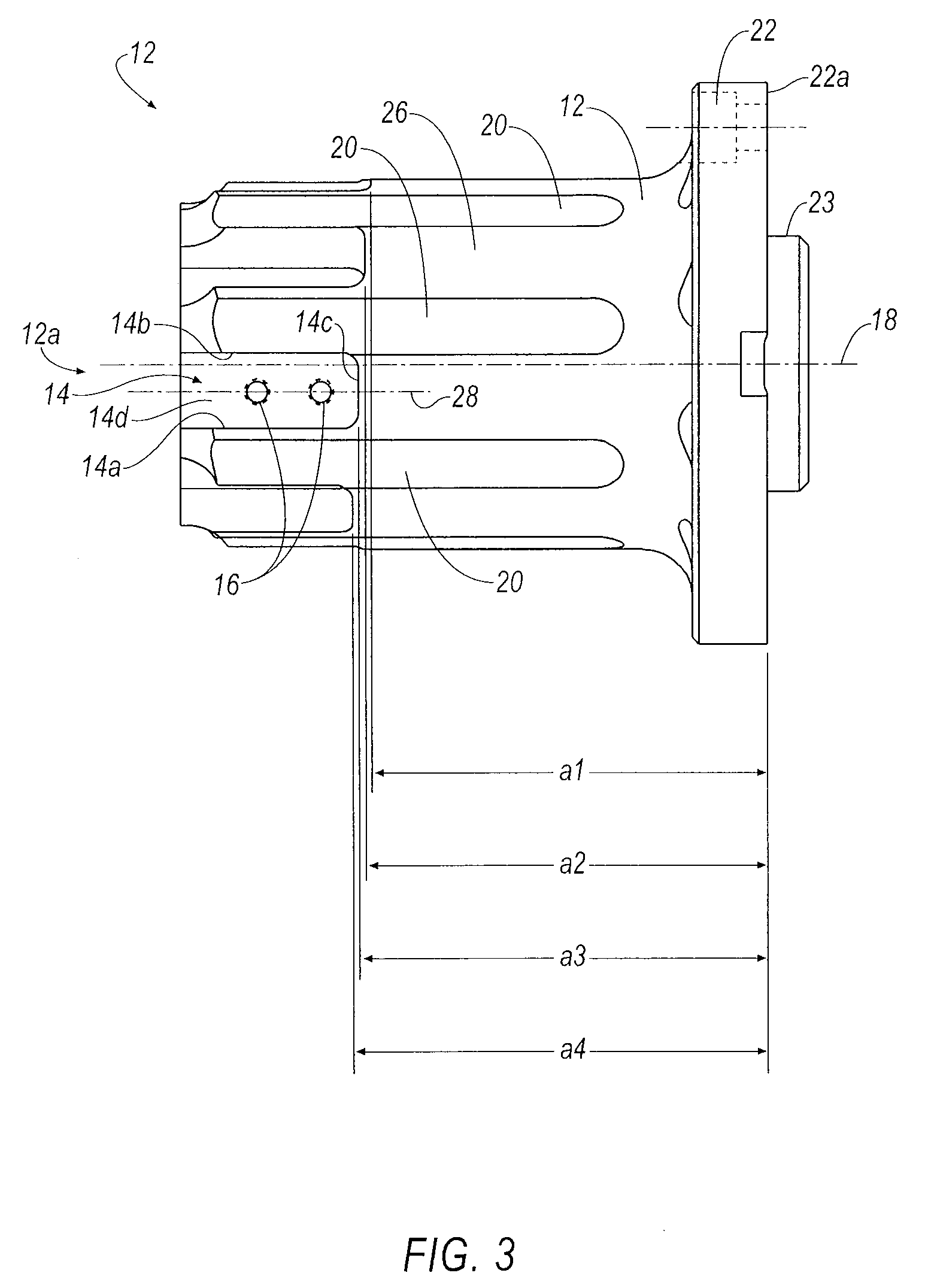
[0025]According to the principles of the invention, a cutting tool includes a body with an even number of cartridge-receiving pockets greater than four pockets, for example, six, eight, ten, twelve, and the like, proximate a cutting end of the body. It is possible that the cutting tool may have an odd number of pockets greater than four pockets, such as five, seven, nine, eleven, and the like. The pockets are spaced circumferentially equidistant with respect to each other. Each cartridge-receiving pocket including a pair of side walls, a bottom wall and a back wall. The back wall of the cartridge-receiving pockets is located at a plurality of different radial distances, and the bottom wall of the cartridge-receiving pockets is located at a plurality of different axial distances. An insert-receiving cartridge is adapted to be mounted to a respective cartridge-receiving pocket. A cutting insert is adapted to be mounted to a respective insert-receiving cartridge. A first group of cutti...


PUM

PropertyMeasurementUnit
diameteraaaaaaaaaa
radial distancesaaaaaaaaaa
axial distancesaaaaaaaaaa

Abstract

A multi-cartridge cutting tool includes a body with a plurality of cartridge-receiving pockets, and a plurality of insert-receiving cartridges mounted to a respective pocket. A round cutting insert is mounted to each cartridge. The pockets are formed at predetermined distances from a central, longitudinal axis of the body to form a first group and a second group of cutting inserts such that the cutting edges of the first group of cutting inserts and the cutting edges of the second group of cutting inserts are located at different axial and radial distances from the central, longitudinal axis of the body to perform different machining operations. A third group of cutting insert(s) may exist for cutting tools with an odd number of cutting inserts. The different types of machining pockets allow for high feed rates, while greatly improving the life of the cutting insert as compared to conventional cutting tools. A railway wheel boring assembly is also disclosed.

Description

[0001]This application is a continuation-in-part of application Ser. No. 12 / 101,172, filed Apr. 11, 2008, the entire contents of which are incorporated herein by reference.BACKGROUND OF THE INVENTION[0002]Cutting tools with round cutting inserts, such as milling cutters, boring bars, and the like, may often manage a number of profiling operations from fine machining to rough machining. Usually, the round cutting inserts generate a fine surface at a particular feed rate because the round edge functions as a wiper. Currently, cutting tools include four round cutting inserts mounted onto the cutter body with two cutting inserts performing a rough cutting operation and the other two cutting insets performing a finish cutting operation. However, it has been observed with cutting tools having four round cutting inserts that the feed rates and the life of the cutting inserts are deficient for some machining applications and some particular materials to be machined. Thus, there is a need to...

Claims


Application Information

Patent Timeline
Patent Type & Authority Applications(United States)
IPC IPC(8): B23B41/00
CPCB23B5/28B23B29/03B23B2200/0461B23B2229/08B23B2229/12B23B2220/445Y10T408/906Y10T407/19Y10T408/36Y10T407/2214Y10T408/905Y10T408/04Y10T408/03
Inventor LYSOBEY, PAUL WILLIAMCHESNEY, DAN ELWYNSTRICKLAND, JAMES H.
Owner KENNAMETAL INC
Why Eureka
Try Eureka