Polar modulation transmission apparatus and polar modulation transmission method

a transmission apparatus and polar modulation technology, applied in the direction of modulation, simultaneous amplitude and angle modulation, transmission, etc., can solve the problems of jamming signals to adjacent frequency bands, degrading the linear characteristics of high frequency power amplifiers, and insufficient studies for a polar modulation transmission apparatus

Active Publication Date: 2009-10-15
PANASONIC CORP
View PDF20 Cites 69 Cited by
  • Summary
  • Abstract
  • Description
  • Claims
  • Application Information

AI Technical Summary

Benefits of technology

[0011]It is therefore an object of the present invention to provide a polar modulation transmission apparatus and polar modulation transmission method that can control the output power of a transmission signal over a wide range, and that can compensate characteristic degradation reliably upon temperature change.

Problems solved by technology

Due to this, linear characteristics of the high frequency power amplifier degrade, and, consequently, a problem arises that, for example, jamming signals to adjacent frequency bands are produced.
However, studies are not sufficiently underway for a polar modulation transmission apparatus that can control the output power of a transmission signal over a wide range and suppress degradation of signal quality due to temperature change.

Method used


Image

  • Polar modulation transmission apparatus and polar modulation transmission method
  • Polar modulation transmission apparatus and polar modulation transmission method
  • Polar modulation transmission apparatus and polar modulation transmission method

Examples


embodiment

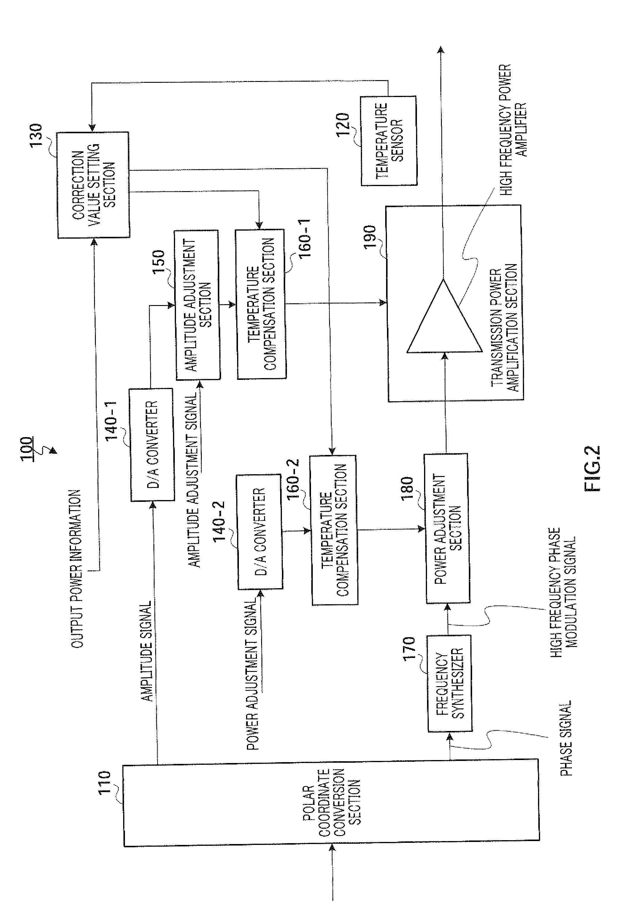
[0030]FIG. 2 illustrates main components of the polar modulation transmission apparatus according to an Embodiment of the present invention. Polar modulation transmission apparatus 100 in FIG. 2 is provided with polar coordinate conversion section 110, temperature sensor 120, correction value setting section 130, D / A (Digital to Analog) converters 140-1 and 140-2, amplitude adjustment section 150, temperature compensation sections 160-1 and 160-2, frequency synthesizer 170, power adjustment section 180 and transmission power amplification section 190.

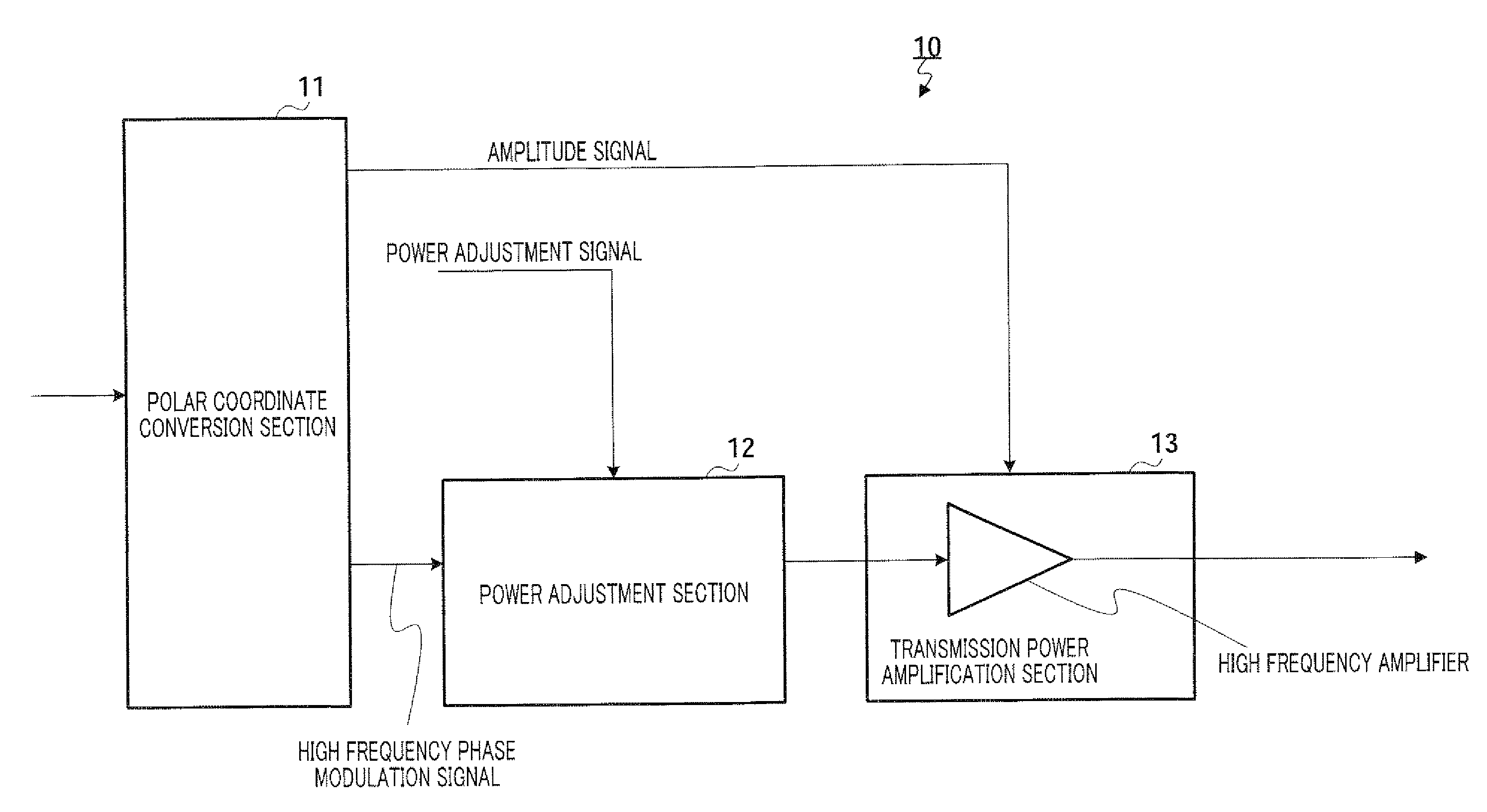
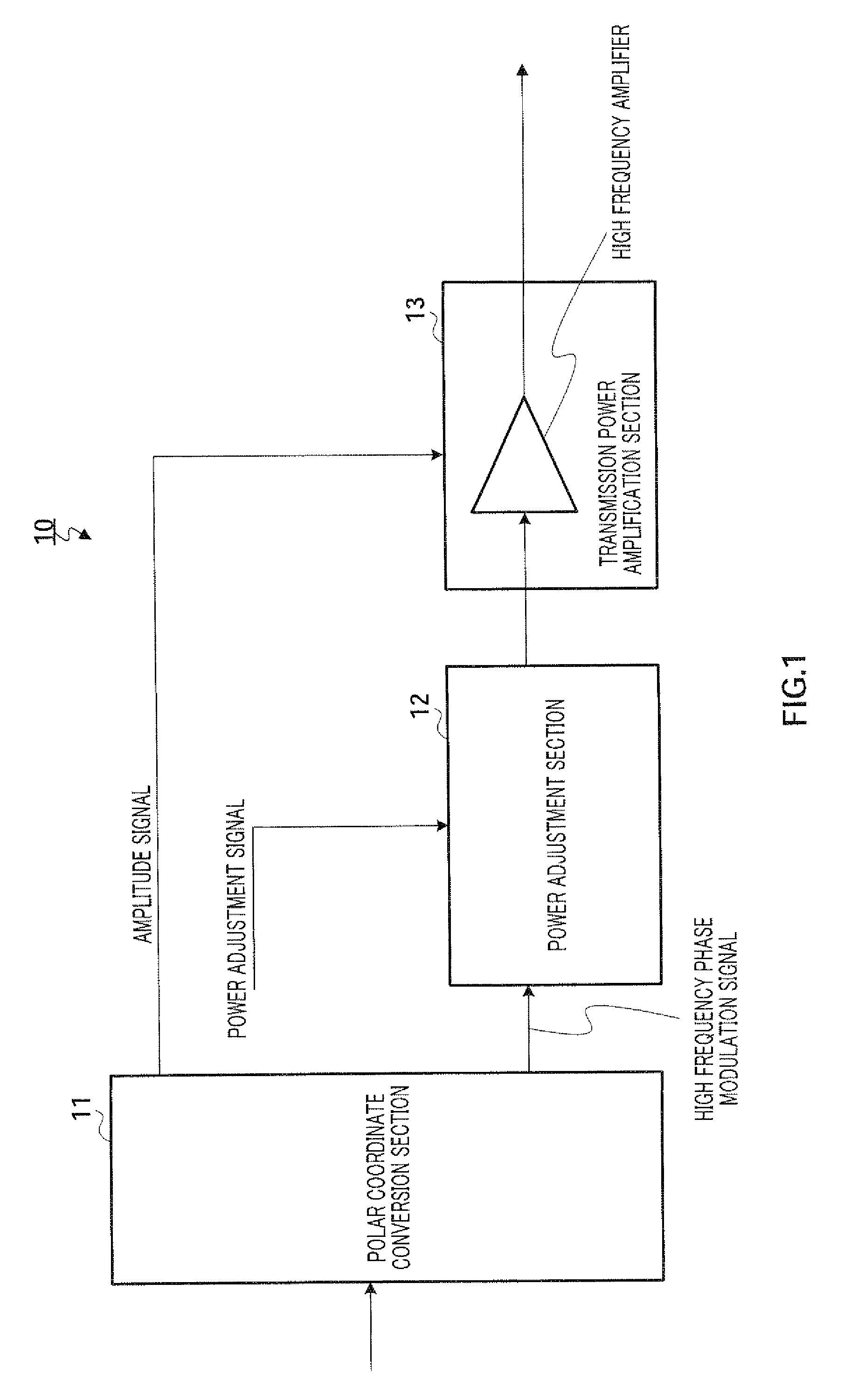
[0031]Polar coordinate conversion section 110 generates an amplitude signal and a phase signal from a modulation signal received as input. To be more specific, polar coordinate conversion section 110 generates an envelope component signal including amplitude information of the modulation signal (i.e., amplitude signal) and a phase signal including phase information of the modulation signal. Polar coordinate conversion section 110 output...


PUM


Abstract

The polar modulation apparatus of the present invention can control the output power of a transmission signal over a wide range and compensate characteristic degradation reliably upon temperature change. Polar modulation transmission apparatus 100 is provided with: temperature sensor 120; temperature compensation section 1601 that corrects an amplitude signal and performs temperature compensation for transmission power amplification section 190; temperature compensation section 160-2 that corrects a power amplification signal and performs temperature compensation for power adjustment section 180; and correction value setting section 130 that sets correction values for temperature compensation section 160-1 and temperature compensation section 160-2, and, while only the amplitude signal is corrected according to a measurement result in temperature sensor 120 in the first mode, the amplitude signal and the power adjustment signal are corrected according to a measurement result in the second mode.

Description

CROSS REFERENCE TO RELATED APPLICATIONS[0001]The disclosures of Japanese Patent Application No. 2008-102799 filed on Apr. 10, 2008, and Japanese Patent Application No. 2009-15330 filed on Jan. 27, 2009, including the specifications, drawings and abstracts, are incorporated herein by reference in their entireties.BACKGROUND OF THE INVENTION[0002]1. Field of the Invention[0003]The present invention specifically relates to a transmission apparatus and polar modulation method using a polar modulation scheme.[0004]2. Description of the Related Art[0005]Upon designing a transmission modulation apparatus in digital radio communication, high efficiency is generally required. However, for the high frequency power amplifier (“PA”) having the largest power consumption in a transmission modulation apparatus, linear characteristics of little distortion are further required in addition to efficiency. For these requirements, a technique has been proposed that enables both efficiency and linearity ...

Claims


Application Information

Patent Timeline
Patent Type & Authority Applications(United States)
IPC IPC(8): H04B1/02H04B1/04
CPCH03C5/00H04B1/0475H03F2200/447H03F1/0222
Inventor NAKAMURA, MAKIISHIDA, KAORU
Owner PANASONIC CORP
Why Eureka
Try Eureka