
Valve Body with Dual Sense Mechanism

a valve body and mechanism technology, applied in the direction of fluid pressure control, process and machine control, instruments, etc., can solve the problems of insufficient application of internal sensing for secondary devices, inconvenient maintenance of piping downstream lines, and high cos

Active Publication Date: 2009-10-22
EMERSON PROCESS MANAGEMENT REGULATOR TECH INC
View PDF28 Cites 46 Cited by
  • Summary
  • Abstract
  • Description
  • Claims
  • Application Information

AI Technical Summary

Benefits of technology

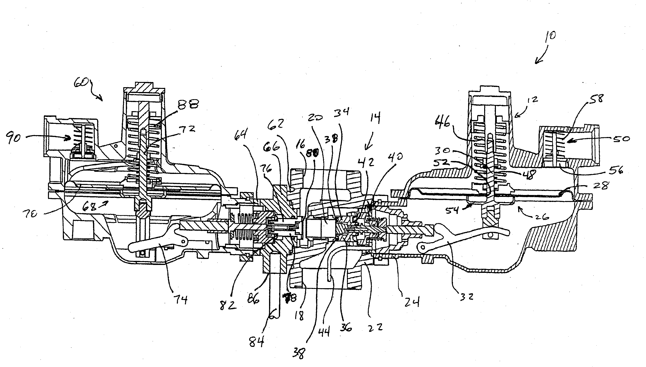
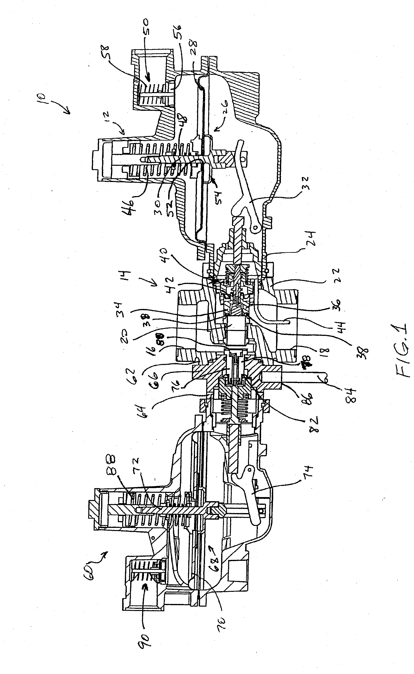
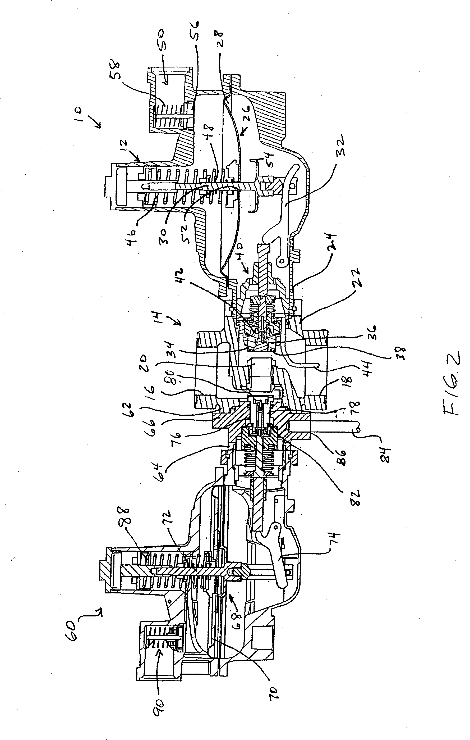
[0016]In one aspect, the invention is directed to a fluid regulating device that may include a regulator valve having an inlet, an outlet, and a valve port disposed between the inlet and the outlet, an actuator coupled to the regulator valve and comprising an actuator valve disc, the actuator valve disc disposed within the regulator valve and adapted for displacement between a closed position engaging a downstream side of the valve port and an open position disposed away from the valve port, and a secondary device coupled to the regulator valve and configured to sense an input pressure and to perform a responsive action if the sensed input pressure varies from a secondary device setpoint pressure. The fluid regulating device may further include a Pitot tube having a first end with a sensing point disposed within the outlet of the regulator valve, a first branch extending t

Problems solved by technology

Presently, such internal sensing has not been widely applied for secondary devices such as the monitoring device 60.
External sensing for secondary devices presents various problems.
For example, piping downstream lines requires additional maintenance and can be costly for gas companies having many regulators in the field.
Additionally, exposed downstream lines, if damaged, make the secondary devices inoperable.
If the secondary device cannot sense the downstream pressure, the secondary device cannot cut off the fluid flow or otherwise signal that a problem exists, thereby leading the operators to the incorrect assumption that the regulator 10 is operating properly.
While being effective at conditioning the flow, the flow conditioning subassembly is relatively expensive to fabricate.
Moreover, the subassembly requires significant and costly modifications to the standard regulator valve body and is not readily transitioned to other body sizes.

Method used


Image

  • Valve Body with Dual Sense Mechanism
  • Valve Body with Dual Sense Mechanism
  • Valve Body with Dual Sense Mechanism

Examples


Embodiment Construction

[0032]Although the following text sets forth a detailed description of numerous different embodiments of the invention, it should be understood that the legal scope of the invention is defined by the words of the claims set forth at the end of this patent. The detailed description is to be construed as exemplary only and does not describe every possible embodiment of the invention since describing every possible embodiment would be impractical, if not impossible. Numerous alternative embodiments could be implemented, using either current technology or technology developed after the filing date of this patent, which would still fall within the scope of the claims defining the invention.

[0033]It should also be understood that, unless a term is expressly defined in this patent using the sentence “As used herein, the term ‘______’ is hereby defined to mean . . . ” or a similar sentence, there is no intent to limit the meaning of that term, either expressly or by implication, beyond its ...


PUM


Abstract

A gas regulator includes an actuator, a regulator valve, and a secondary device. Downstream pressure feedback is provided to the actuator and the secondary device via a Pitot tube disposed within an outlet of the regulator valve. The Pitot tube has a first branch having an end connected to the actuator to place the actuator control cavity and diaphragm in fluid communication with downstream pressure within the outlet for maintaining the outlet pressure at an actuator setpoint pressure. The Pitot tube also has a second branch having an end connected to the secondary device to place the interior of the secondary device in fluid communication with downstream pressure within the outlet for responding to changes in the downstream pressure when the outlet pressure diverges from a predetermined normal operating pressure range.

Description

CROSS-REFERENCE TO RELATED APPLICATIONS[0001]This application claims the benefit of priority to U.S. Provisional Patent Application No. 61 / 046,788, filed on Apr. 21, 2008, entitled “Valve Body with Dual Sense Mechanism,” which is hereby expressly incorporated by reference hereinFIELD OF THE INVENTION[0002]The present invention relates to fluid flow regulating devices such as gas regulators and, more particularly, to gas regulators having secondary devices sensing the same pressure from the same points of the devices, such as overpressure monitoring devices, slam shut devices, token alarm devices, and the like.BACKGROUND[0003]The pressure at which typical gas distribution systems supply gas may vary according to the demands placed on the system, the climate, the source of supply, and / or other factors. However, most end-user facilities equipped with gas appliances such as furnaces, ovens, etc., require the gas to be delivered in accordance with a predetermined pressure, and at or belo...

Claims


Application Information

Patent Timeline
IPC IPC(8): F16K17/34
CPCG05D16/0694G05D16/0605G05D16/02G05D16/0404Y10T137/7795Y10T137/7831Y10T137/7754Y10T137/7757Y10T137/7794
Inventor MEVIUS, JASON S.HAWKINS, JAMES C.KRANZ, SETH A.FOUST, GREGORY L.
Owner EMERSON PROCESS MANAGEMENT REGULATOR TECH INC
Learn More