Vertebral interbody compression implant

a technology of interbody and implant, which is applied in the field of skeletal stabilization systems, can solve the problems of difficult surgical access to the locations between the vertebrae where the spacer is to be installed, and achieve the effect of improving the stability of the implan

Active Publication Date: 2009-10-22
INNOVATIVE SPINAL TECH +1
View PDF1 Cites 217 Cited by
  • Summary
  • Abstract
  • Description
  • Claims
  • Application Information

AI Technical Summary

Problems solved by technology

Although prior interbody devices, including spacers, may be effective at improving the condition of a patient, the vertebrae of the spine, body organs, the spinal cord,

Method used


Image

  • Vertebral interbody compression implant
  • Vertebral interbody compression implant
  • Vertebral interbody compression implant

Examples


Embodiment Construction

[0022]Specific examples of components, methods, and arrangements are described below to simplify the present disclosure. These are, of course, merely examples and are not intended to limit the invention from that described in the claims. Well-known elements are presented without detailed description in order not to obscure the present invention in unnecessary detail. For the most part, details unnecessary to obtain a complete understanding of the present invention have been omitted inasmuch as such details are within the skills of persons of ordinary skill in the relevant art.

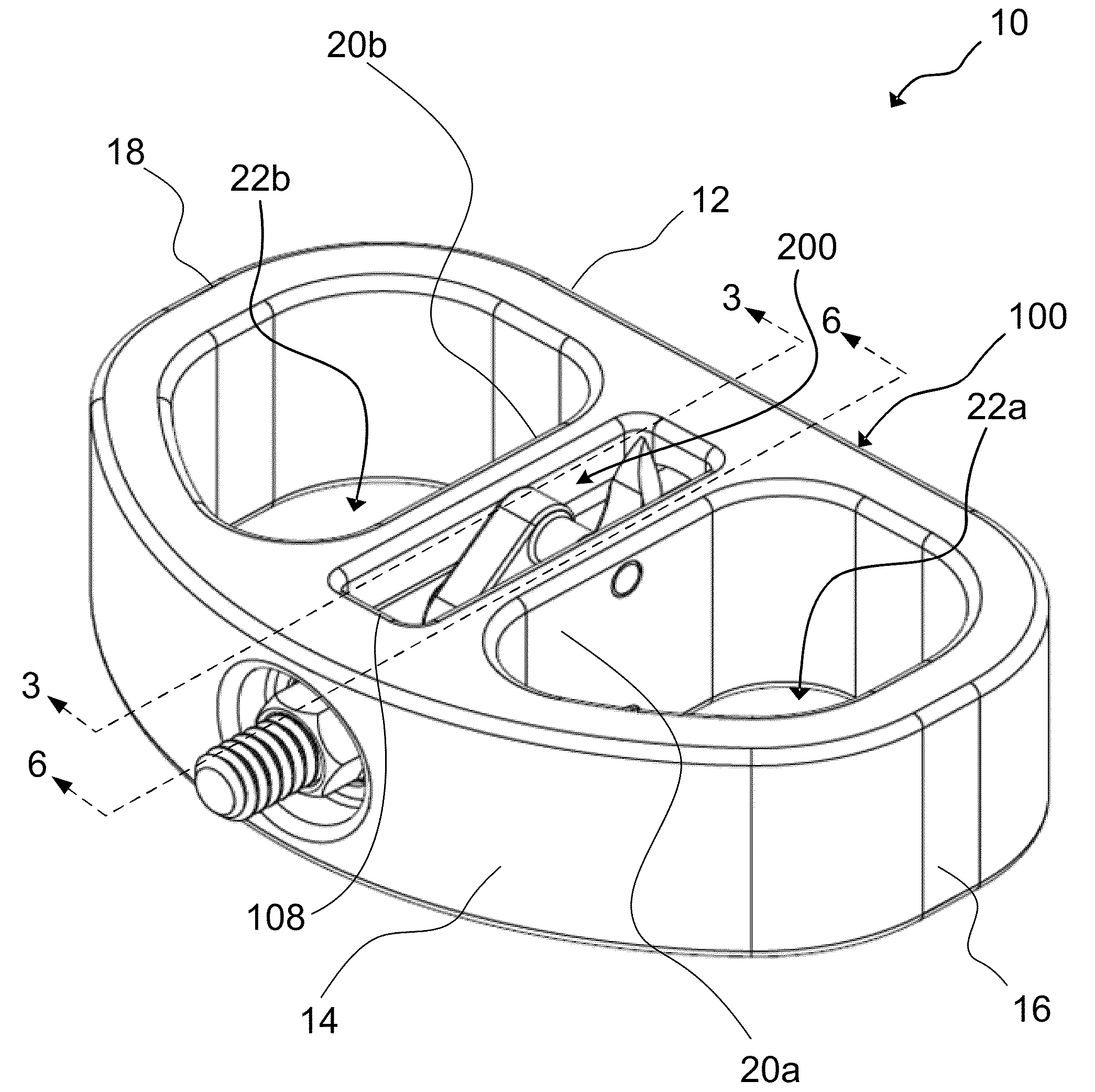
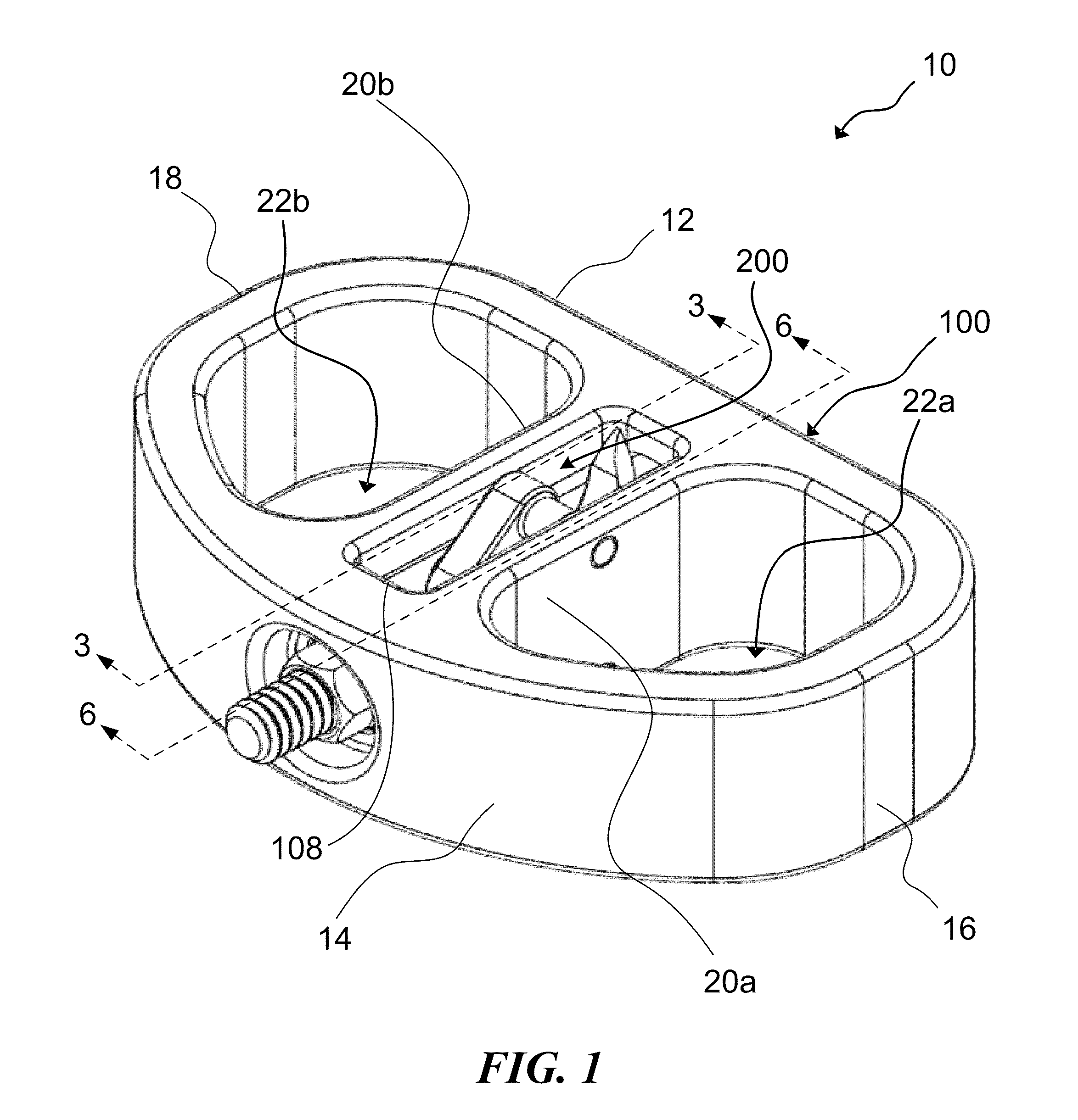
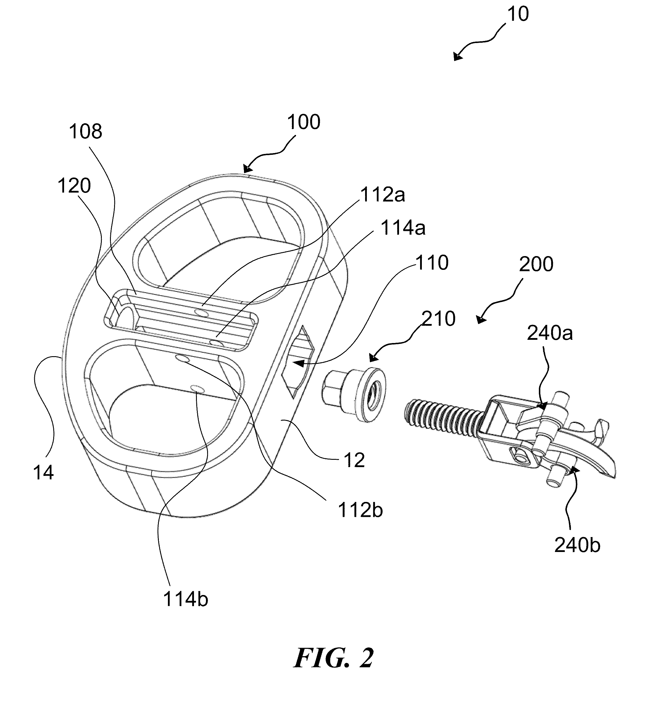
[0023]Turning now to FIG. 1, there is presented a front perspective view of one possible embodiment of a perspective view of a vertebral interbody compression implant 10. The implant 10 may incorporate a main body 100 and a compression mechanism 200. The implant 10 may be inserted between two adjacent bony structures (for example two adjacent vertebrae of the spine) using various instruments to stabilize or fus...


PUM


Abstract

An apparatus and method for securing boney structures is disclosed which includes a compression mechanism and a force transfer mechanism. The compression mechanism may have bone engagement members that have one portion slideably coupled to a housing positioned within the implant and another portion rotatably coupled to the implant so that a movement of the housing causes the slideable portion to move within the housing and a penetrating member to rotate about the rotatably coupled portion. The force transfer mechanism may be coupled to the compression mechanism to move the housing.

Description

CROSS-REFERENCE TO RELATED APPLICATIONS[0001]This application relates to, and claims the benefit of the filing date of, co-pending U.S. provisional patent application Ser. No. 60 / 987,111 entitled VERTEBRAL INTERBODY COMPRESSION IMPLANT, filed Nov. 12, 2007, the entire contents of which are incorporated herein by reference for all purposes.BACKGROUND INFORMATION[0002]The invention relates in general to skeletal stabilization systems, and in particular to implants, surgical guides, delivery instruments and methods for delivering and attaching implants to bony structures such as a vertebrae.[0003]The human spine is a complex structure designed to achieve a myriad of tasks, many of them of a complex kinematic nature. The spinal vertebrae allow the spine to flex in three axes of movement relative to the portion of the spine in motion. These axes include the horizontal (i.e., bending either forward / anterior or aft / posterior), roll (i.e., lateral bending to either left or right side), and ...

Claims


Application Information

Patent Timeline
IPC IPC(8): A61F2/44A61B17/58
CPCA61F2/4465A61F2/4611A61F2002/2835A61F2002/30471A61F2220/0091A61F2002/30579A61F2002/30772A61F2220/0025A61F2002/30507
Inventor COLLERAN, DENNIS
Owner INNOVATIVE SPINAL TECH
Why Eureka
Try Eureka