High Pressure Tube Seal

Inactive Publication Date: 2009-10-29
FREUDENBERG NOK GEN PARTNERSHIP
View PDF37 Cites 10 Cited by
  • Summary
  • Abstract
  • Description
  • Claims
  • Application Information

AI Technical Summary

Benefits of technology

[0004]An improvement to this sealing solution was patented in Europe (DE19548249C2 and DE19902953A1) by FDS Reichelsheim by directly molding rubber to an adhesive covered tube. This technique allowed for l

Problems solved by technology

This design has been found to have two main deficiencies; the first being the seal's inability to compensate for offset between the two bores and the second being va

Method used


Image

  • High Pressure Tube Seal
  • High Pressure Tube Seal
  • High Pressure Tube Seal

Examples


Embodiment Construction

[0016]The following description is merely exemplary in nature and is not intended to limit the present disclosure, application, or uses. It should be understood that throughout the drawings, corresponding reference numerals indicate like or corresponding parts and features.

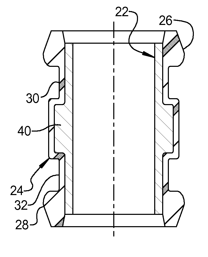
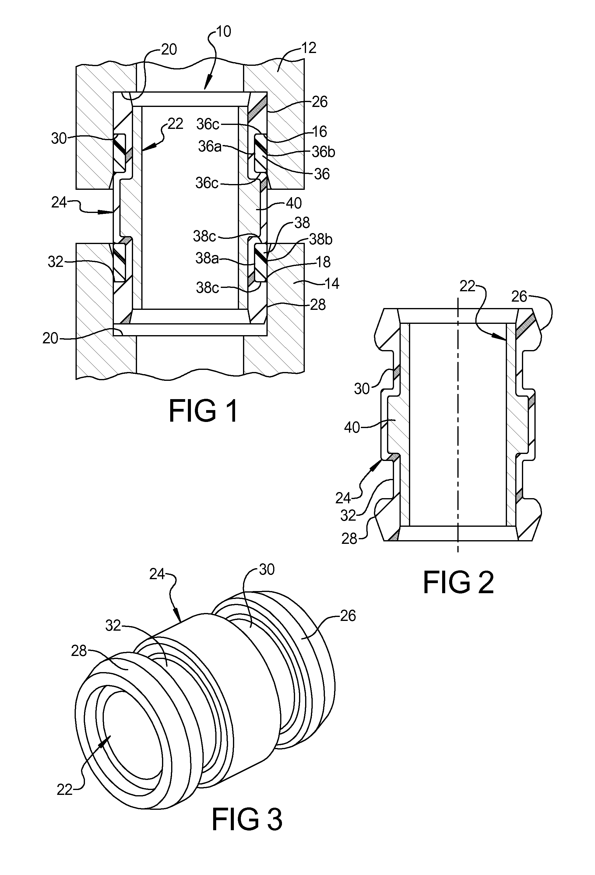
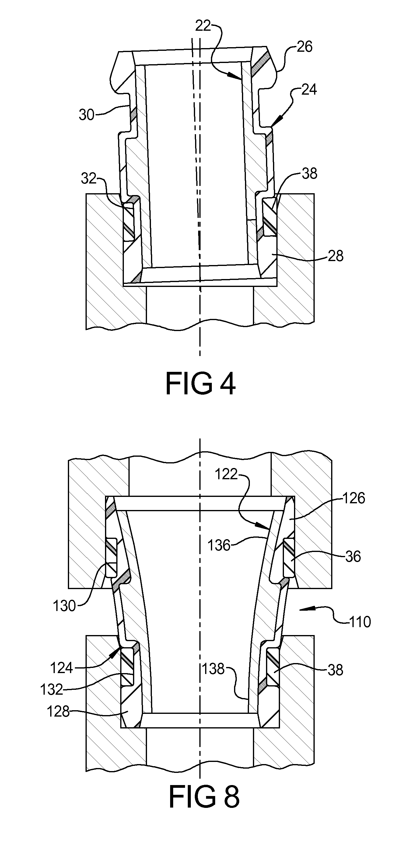
[0017]With reference to FIG. 1, a tube seal 10 is shown providing a seal connection between a first tube member 12 and a second tube member 14. First tube member 12 can include an interior surface 16 and second tube member 14 can include an interior surface 18 and each tube member 12, 14 can include a shoulder portion 20 extending radially inward from surfaces 16, 18, respectively. The tube seal 10 sealingly engages against interior surfaces 16 and 18 of first and second tube members 12, 14.

[0018]The tube seal 10 can include a rigid cylindrical tube 22 and an elastomeric seal body 24 molded to an outer surface of the cylindrical tube 22. The elastomeric seal body includes a pair of raised seal bead portions 26, 28...


PUM


Abstract

A high pressure tube seal is provided including a rigid cylindrical tube having an elastomeric seal body molded to an outer surface of the cylindrical tube. The elastomeric seal body includes a pair of raised seal bead portions at opposite ends of the seal body and a pair of recessed groove portions adjacent to the pair of recessed seal bead portions. A pair of anti-extrusion rings are disposed in the recessed groove portion in the cylindrical tube and includes a radially outwardly extending annular portion disposed between a pair of recessed groove portions of the elastomeric seal body. The anti-extrusion rings provide increased pressure sealing capability as compared to conventional tube seal designs.

Description

FIELD[0001]The present disclosure relates to tube seals, and more particularly to a high pressure tube seal.BACKGROUND AND SUMMARY[0002]The statements in this section merely provide background information related to the present disclosure and may not constitute prior art.[0003]Historically, the standard method of sealing two joints not directly connected to each other has been to use a tube with an o-ring at each end. This design has been found to have two main deficiencies; the first being the seal's inability to compensate for offset between the two bores and the second being various assembly issues including missing o-rings, cut o-rings, and rolled o-rings.[0004]An improvement to this sealing solution was patented in Europe (DE19548249C2 and DE19902953A1) by FDS Reichelsheim by directly molding rubber to an adhesive covered tube. This technique allowed for large seal beads to be incorporated into the design which would allow for misalignment in the application as well as the elim...

Claims


Application Information

Patent Timeline
IPC IPC(8): F16J15/46
CPCF16L21/022F16L25/14F16L21/035F16L27/1017F16L27/113
Inventor SMITH, TIMOTHY T.SEABORN, DAVID M.
Owner FREUDENBERG NOK GEN PARTNERSHIP
Why Eureka
Try Eureka