Motor rotor and electric power steering apparatus
a technology of electric power steering and motor rotor, which is applied in the direction of dynamo-electric machines, magnetic circuit rotating parts, and shape/form/construction of magnetic circuits, etc., can solve the problems of exacerbating motor characteristics and occurrence of so-called “magnetic leakage” and achieve the effect of improving steering feel
- Summary
- Abstract
- Description
- Claims
- Application Information
AI Technical Summary
Benefits of technology
Problems solved by technology
Method used
Image
Examples
first embodiment
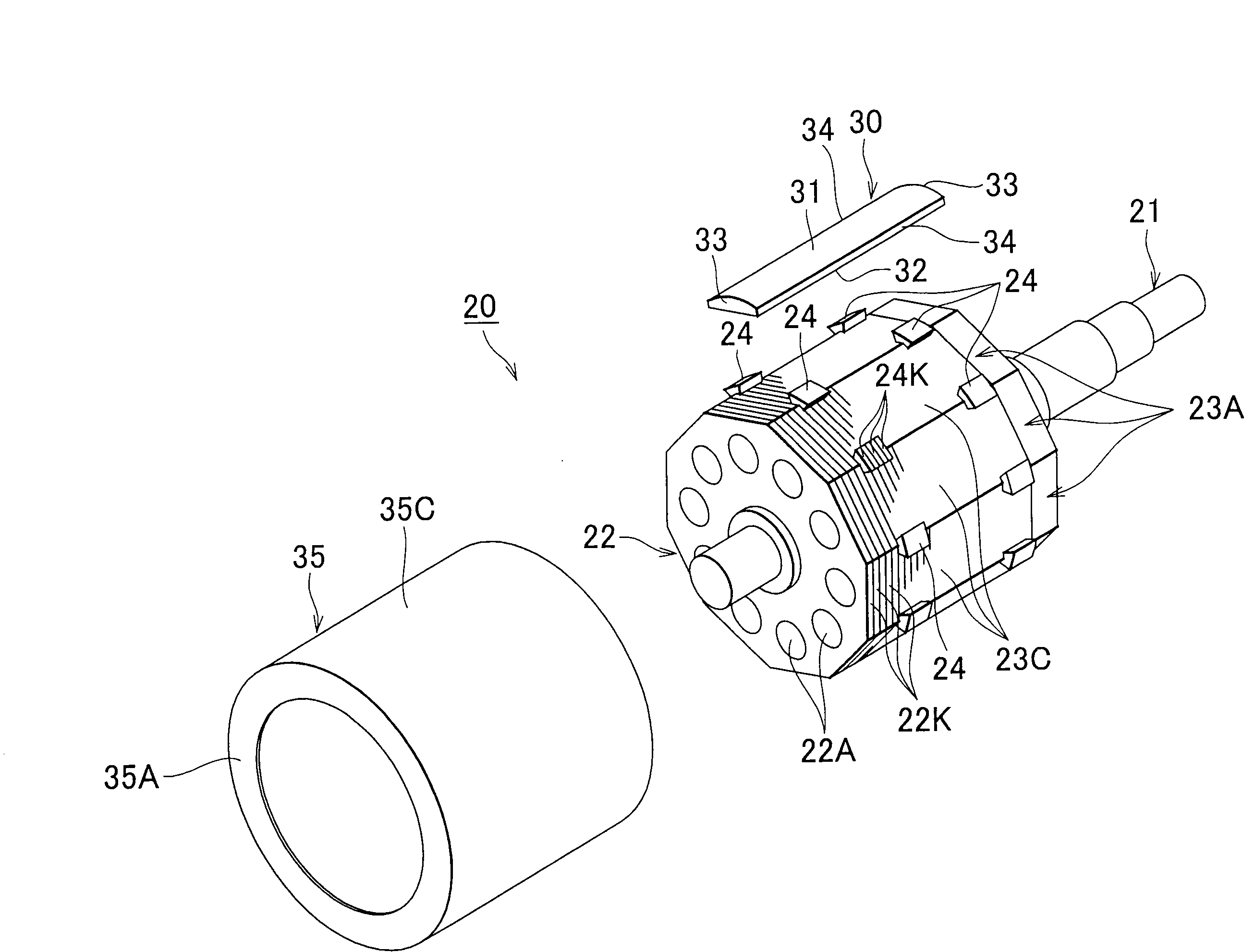
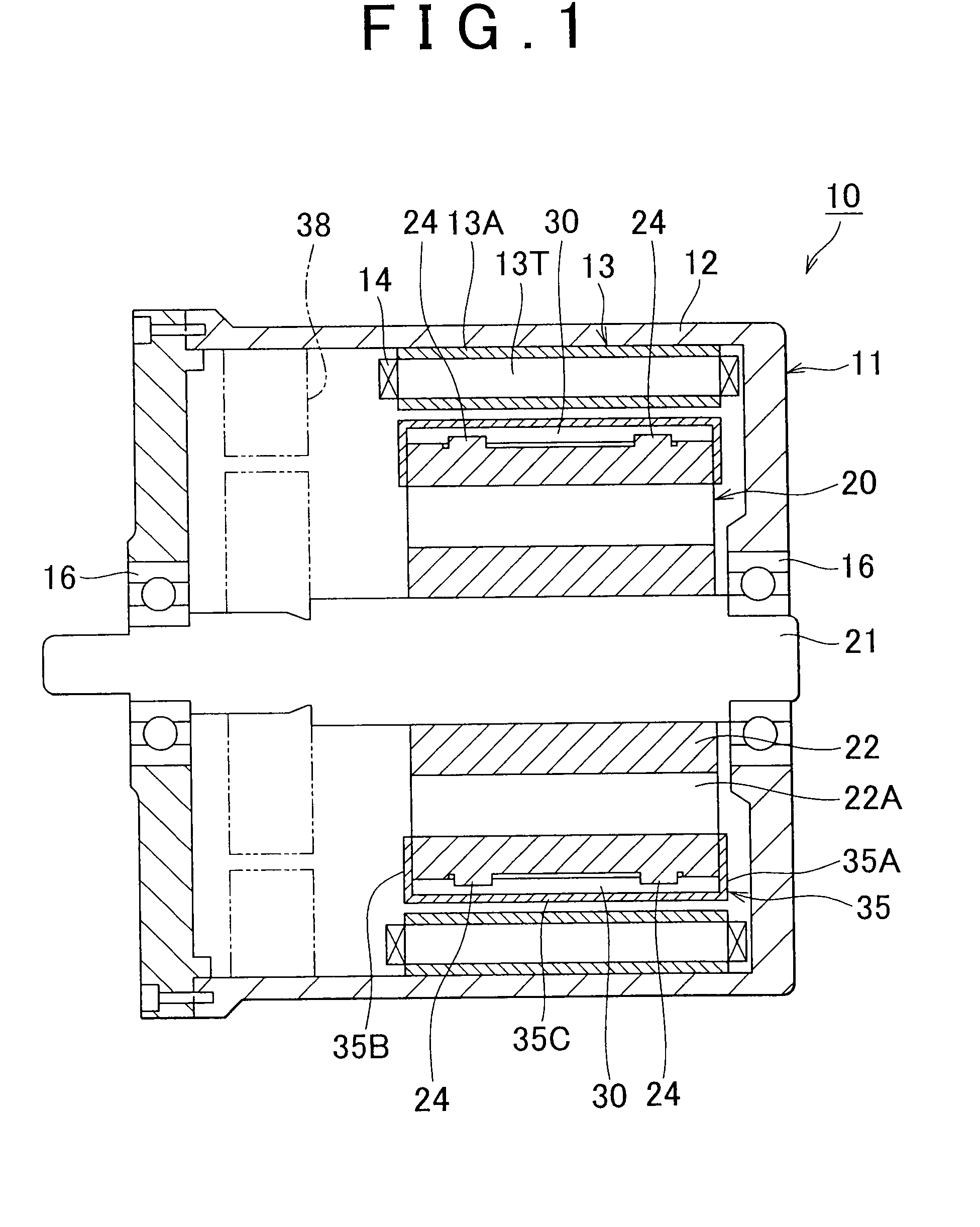
[0033]The following provides an explanation of a first embodiment of the invention based on FIGS. 1 to 4. A motor 10 shown in FIG. 1 is a brushless, three-phase alternating current motor, and a stator 11 of this motor 10 employs a structure in which a stator core 13 is fixed to the inside of a motor housing 12 by engaging therewith. The motor housing 12 has the form of, for example, a cylinder that is closed on both ends. In addition, the stator core 13 has a structure in which a plurality of teeth 13T are protruding radially inward from the inner peripheral surface of a cylindrical body 13A, and electromagnetic coils 14 are respectively wound around each of these teeth 13T.
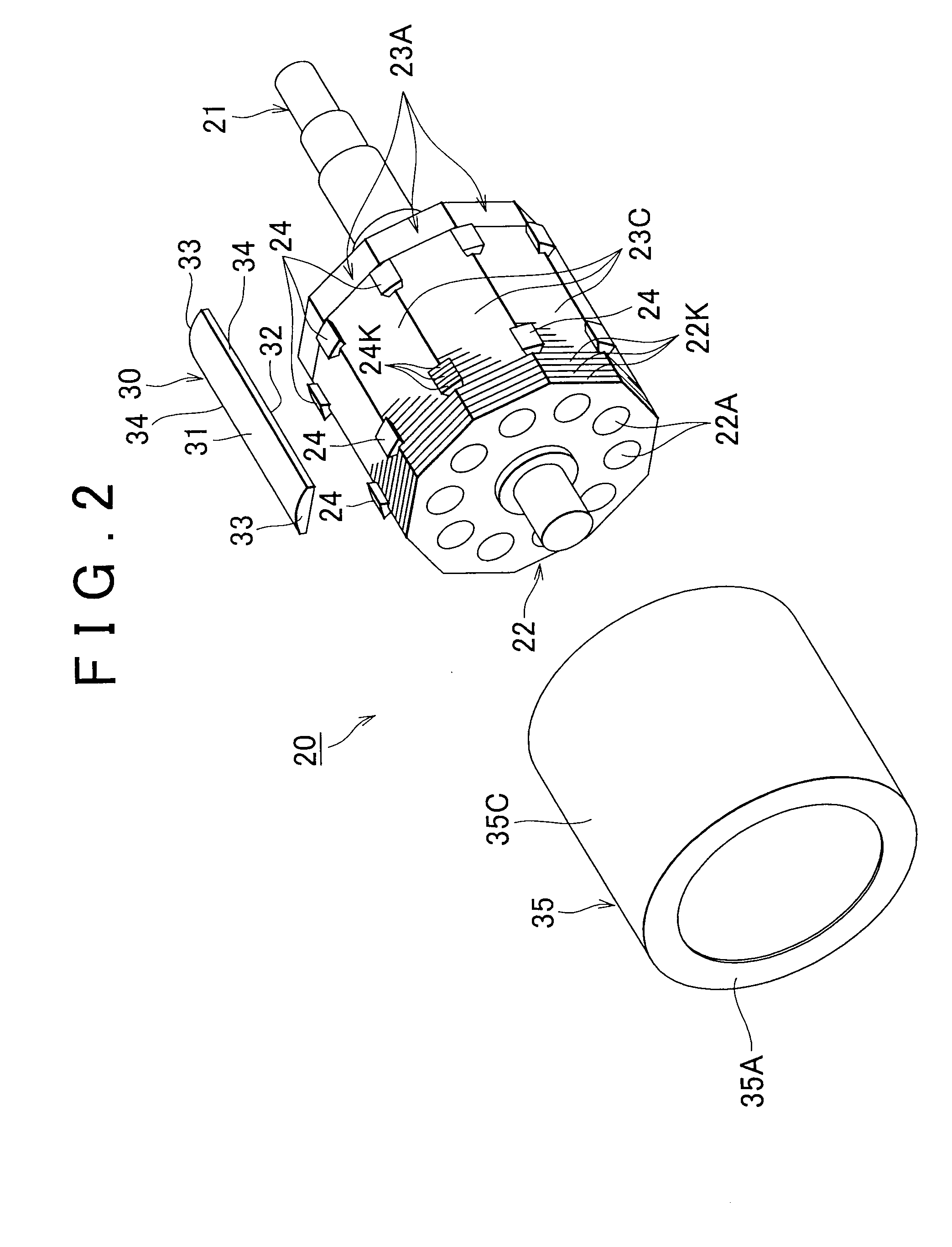
[0034]A rotor 20 of this motor 10 has a structure in which a rotor shaft 21 passes through the center of a rotor yoke 22, and a plurality of segment magnets 30 are fixed to the lateral surface of the rotor yoke 22. As shown in FIG. 2, the segment magnets 30 are roughly in the form of long plates extending in the ...
second embodiment
[0054]The following provides an explanation of an embodiment of an electric power steering apparatus according to the invention. As shown in FIG. 5, an electric power steering apparatus 100 of this embodiment is provided with a turning wheel connecting shaft 102 extending between a pair of turning wheels 101 provided on a vehicle 110, and a shaft case 103 covering the outside of the turning wheel connecting shaft 102. Both ends of the turning wheel connecting shaft 102 are connected to each turning wheel 101 via tie rods 102T, and the shaft case 103 is fixed to the chassis of the vehicle 110. In addition, a rack (not shown) is formed at an intermediate portion of the turning wheel connecting shaft 102, and a pinion (not shown) passing through the intermediate portion of the shaft case 103 from the side meshes with this rack.
[0055]A steering shaft 106 is connected to the upper end of the pinion, and a steering wheel 107 is further connected to the upper end of the steering shaft 106....
PUM
 Abstract
Description
Claims
Application Information
 - R&D
- Intellectual Property
- Life Sciences
- Materials
- Tech Scout
- Unparalleled Data Quality
- Higher Quality Content
- 60% Fewer Hallucinations
Browse by: Latest US Patents, China's latest patents, Technical Efficacy Thesaurus, Application Domain, Technology Topic, Popular Technical Reports.
© 2025 PatSnap. All rights reserved.Legal|Privacy policy|Modern Slavery Act Transparency Statement|Sitemap|About US| Contact US: help@patsnap.com


