[0007]The invention provides a direct injection spark ignition internal
combustion engine and a method for controlling the same, which sufficiently suppresses the production of smoke.
[0009]According to the direct injection spark ignition internal combustion engine of the first aspect of the invention, during fuel injection, the thrust force of the injected fuel is switched between at least two levels such that the thrust force of the injected fuel becomes weaker when the position of the piston is high and therefore the likelihood that the injected fuel will attach the top face of the piston is high than when the position of the piston is low and the same likelihood is low. Therefore, the amount of fuel that would attach the top face of the piston is reduced sufficiently and thus the production of smoke is suppressed sufficiently. According to the direct injection spark ignition internal combustion engine of the first aspect of the invention, further, the thrust force of the injected fuel is strengthened when the position of the piston is low, which promotes the atomization of the injected fuel, so that the injected fuel vaporizes efficiently. This feature eliminates the possibility of a problem that, due to the thrust force of the injected fuel being weak, the overall fuel injection duration is extended to an extent that the time allowed for the
vaporization of the injected fuel before the time of ignition becomes insufficient.
[0015]In the direct injection spark ignition internal combustion engine of the fourth aspect of the invention, in the case where the time period allowed for the
vaporization of the injected fuel before the time of ignition is sufficient when the engine speed is equal to the predetermined engine speed, the thrust force switching piston position is set to the highest position when the engine speed is equal to the predetermined engine speed. Further, as the engine speed decreases below the predetermined engine speed and thus the temperature of the piston decreases accordingly, the
vaporization of the fuel on the top face of the piston becomes sluggish. Therefore, in the direct injection spark ignition internal combustion engine of the fourth aspect of the invention, the thrust force switching piston position is lowered as the engine speed decreases below the predetermined engine speed. Further, as the engine speed increases above the predetermined engine speed, the time period allowed for the vaporization of the fuel on the top face of the piston before the time of ignition shortens. In the direct injection spark ignition internal combustion engine of the fourth aspect of the invention, therefore, the thrust force switching piston position is lowered as the engine speed increases above the predetermined engine speed. As such, the production of smoke can be suppressed.
[0017]As the engine temperature decreases and thus the temperature of the piston decreases accordingly, the vaporization of the fuel on the top face of the piston becomes sluggish. In the direct injection spark ignition internal combustion engine of the fifth aspect of the invention, therefore, the thrust force switching piston position is lowered as the engine temperature decreases. As such, the production of smoke can be suppressed.
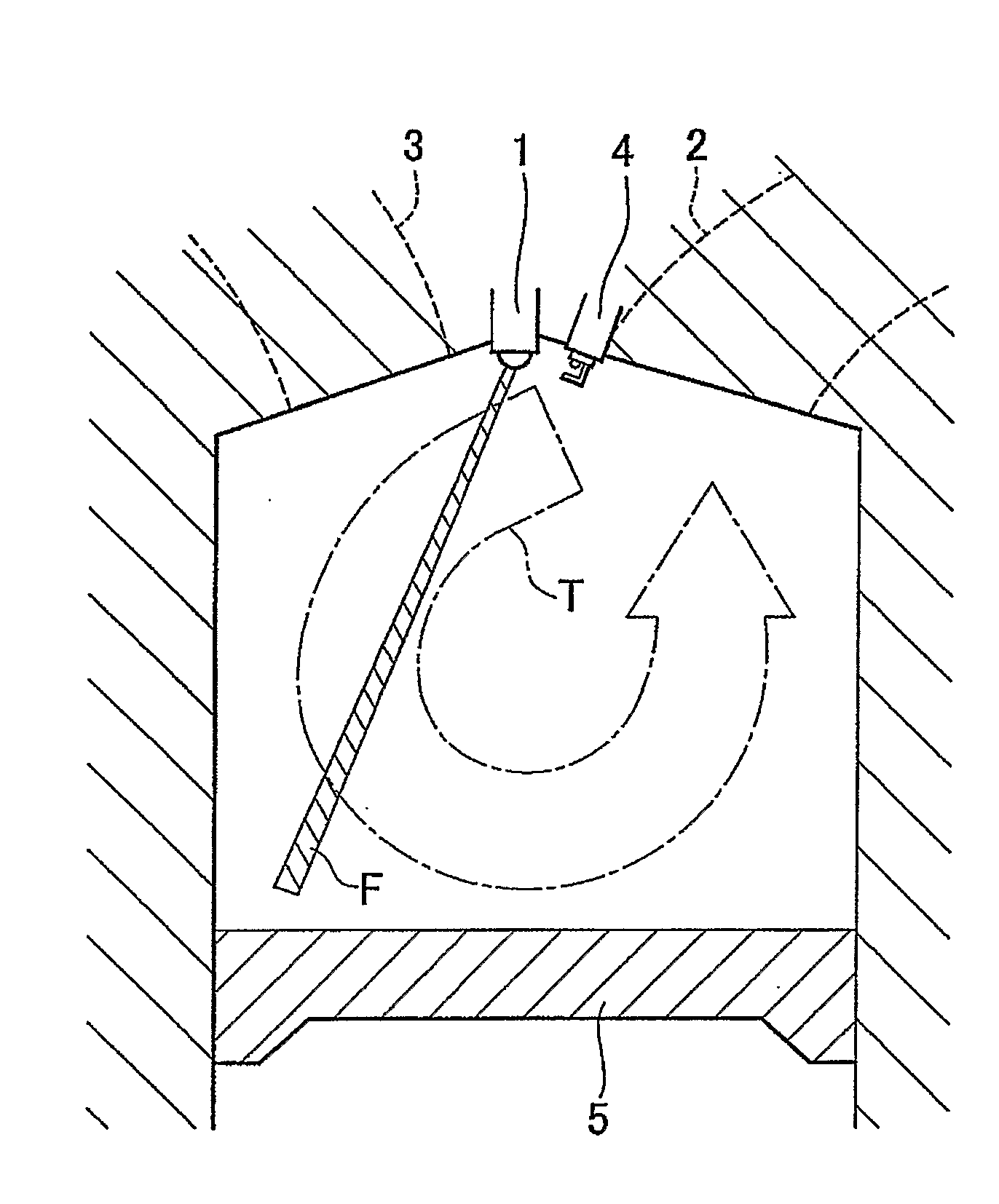
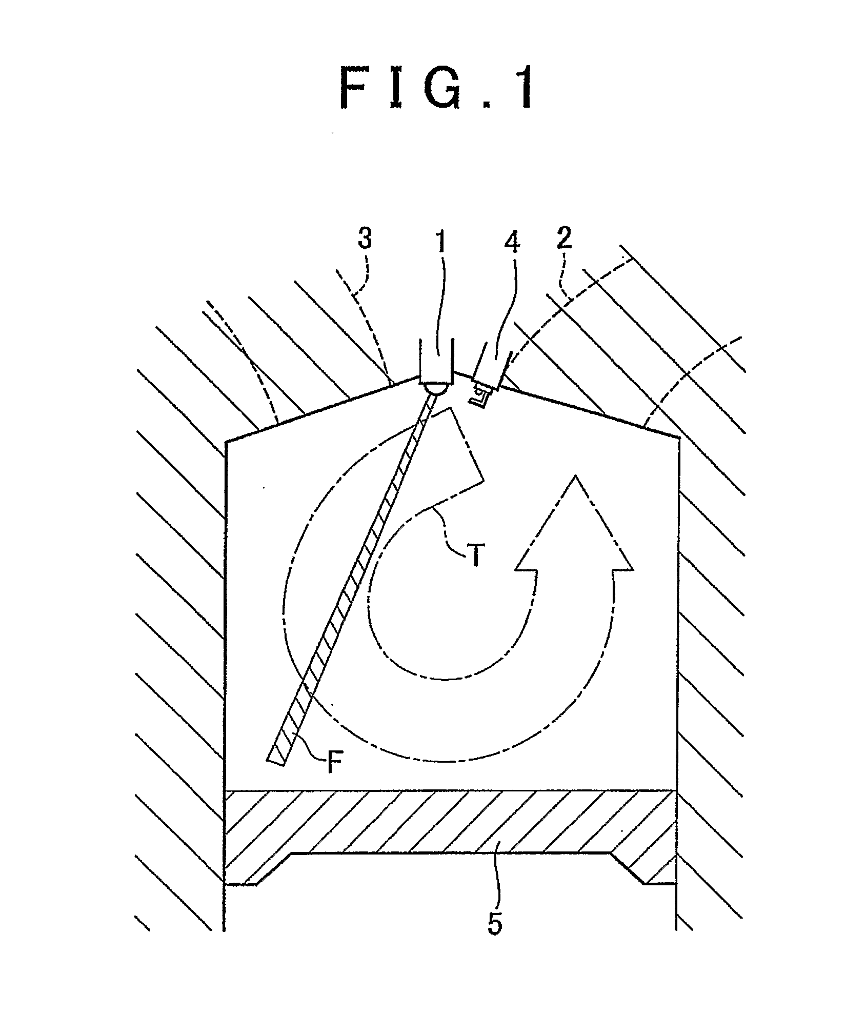
[0019]According to the direct injection spark ignition internal combustion engine of the sixth aspect of the invention, because the internal combustion engine is configured such that the fuel injection valve is provided at substantially the center of the upper area of the engine cylinder or at the
exhaust valve side of the periphery of the upper area of the engine cylinder and the fuel is injected toward the
exhaust valve side of the top face of the piston through the fuel injection valve, the tumble flow flowing downward in the
exhaust valve side of the engine cylinder and upward in the intake valve side can be effectively intensified. In order to intensify the tumble flow such that it remains active until the latter half of the compression
stroke and thus the movement of air-fuel mixture in the engine cylinder remains strong until the time of ignition to increase the combustion speed, the fuel injection duration is preferably fixed to a
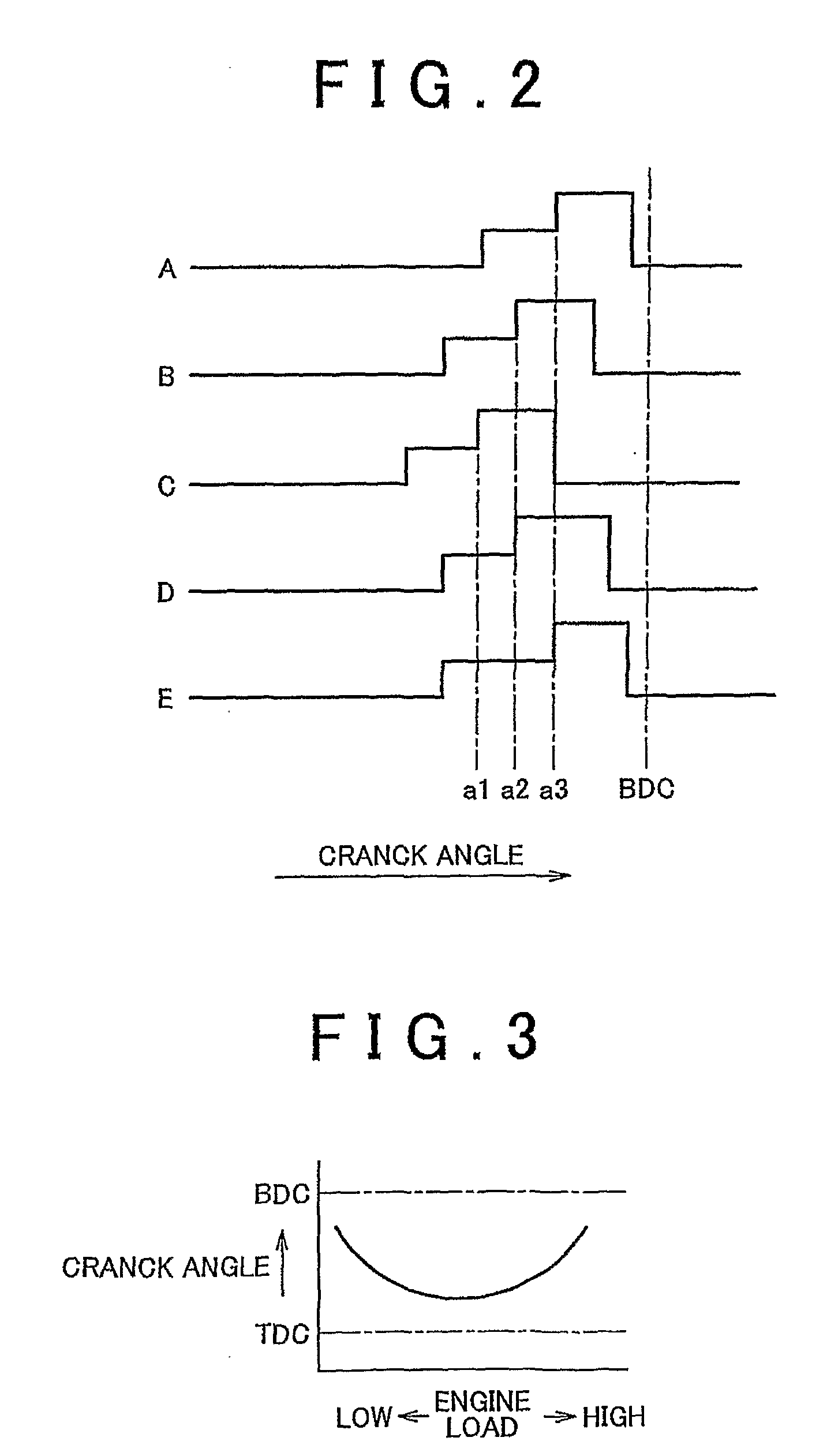
crank angle range where the intake air amount per unit time is large. Therefore, in the direct injection spark ignition internal combustion engine of the sixth aspect of the invention, the fuel injection duration is fixed to a
crank angle range
ranging from the first
crank angle in the middle stage of an intake
stroke as the timing for starting fuel injection to the second crank angle immediately before the bottom dead center on the intake stroke as the timing for ending the fuel injection. Further, in the direct injection spark ignition internal combustion engine of the sixth aspect of the invention, the thrust force of the injected fuel is switched between two levels, and the timing for switching the thrust force of the injected fuel is retarded so that the duration for which fuel is injected with a small thrust force extends while the duration for which fuel is injected with a large thrust force shortens, whereby the fuel injection amount decreases. That is, the required fuel amount can be injected by appropriately setting the timing for switching the thrust force of the injected fuel.

