
Battery cooling structure

Pending Publication Date: 2021-07-15
TOYOTA JIDOSHA KK
View PDF1 Cites 0 Cited by
  • Summary
  • Abstract
  • Description
  • Claims
  • Application Information

AI Technical Summary

Benefits of technology

The patent is about improving cooling for a vehicle's battery while reducing the amount of electromagnetic noise produced by the battery. The goal is to maintain the battery's performance while minimizing interference with other electronic components in the vehicle.

Problems solved by technology

Thus, cooling performance of the cells in the battery described above is not necessarily sufficient.

Method used


Image

  • Battery cooling structure
  • Battery cooling structure
  • Battery cooling structure

Examples


first exemplary embodiment

[0037]First, a battery cooling structure 10 according to a first exemplary embodiment is described.

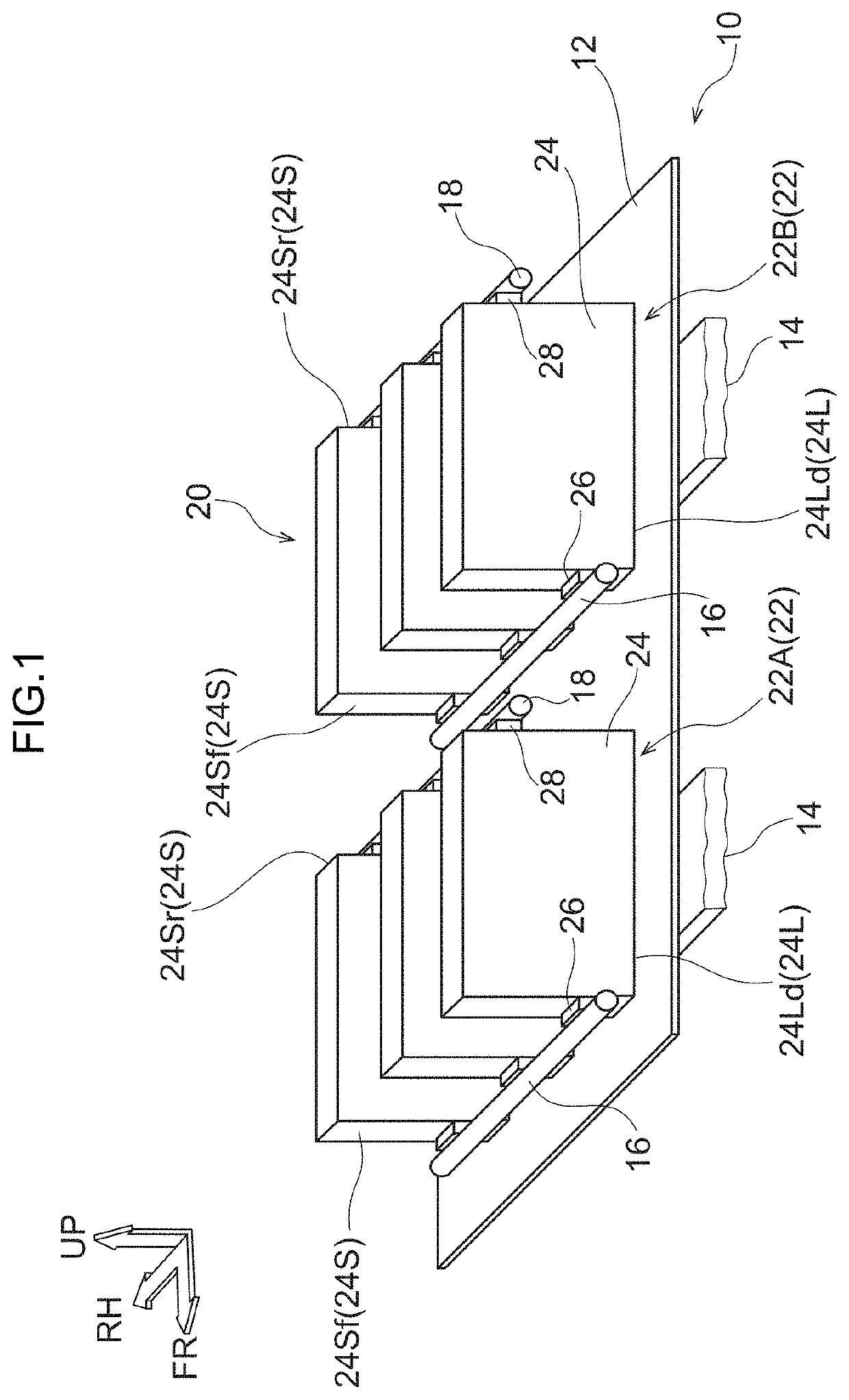
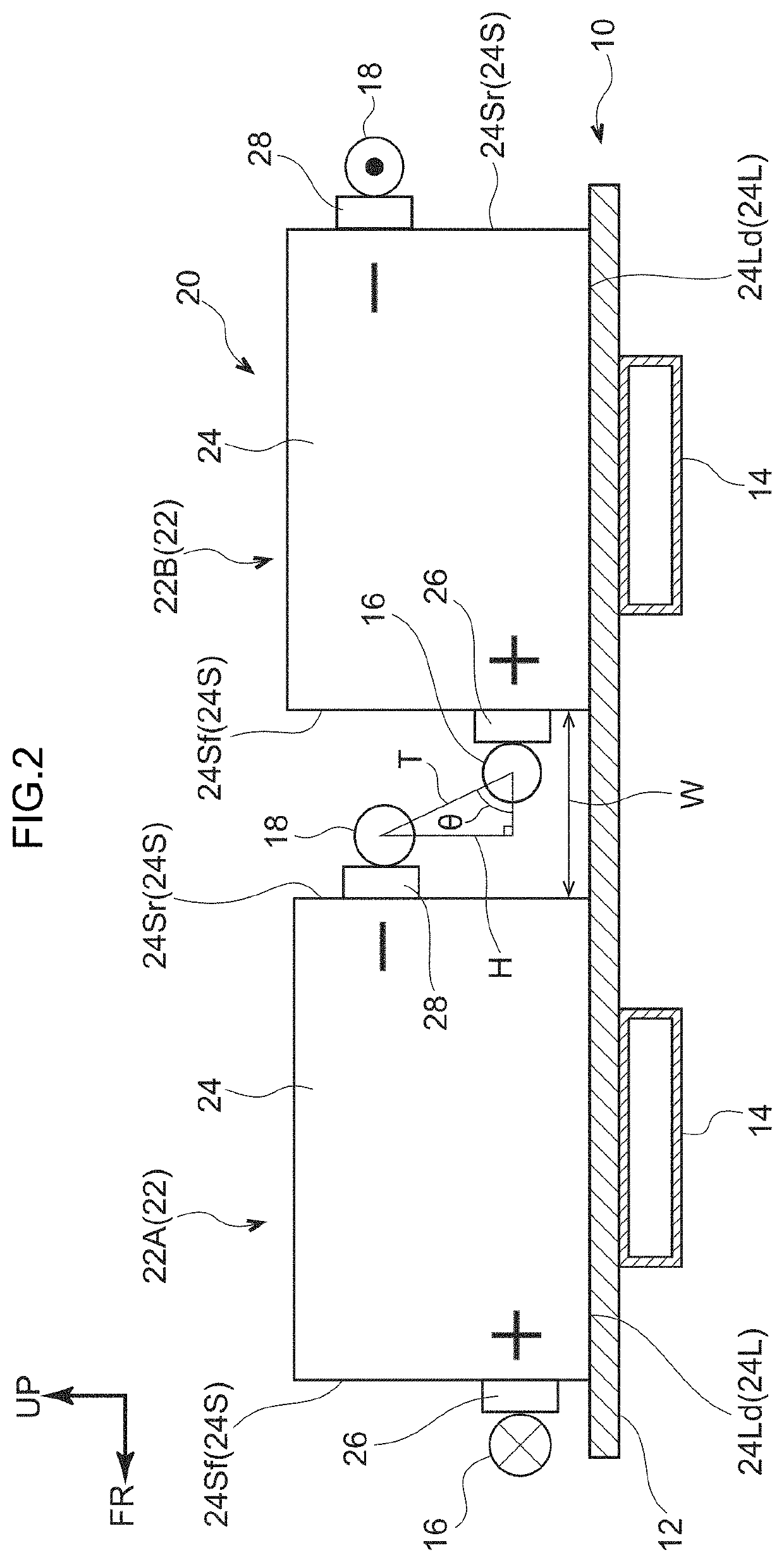
[0038]As shown in FIG. 1 and FIG. 2, a battery cooling structure 10 is provided with a battery 20 below the floor of an electric car that serves as a vehicle. The battery 20 includes cell groups 22, in each of which plural cells 24 are arrayed in a thickness direction thereof at an upper face of a cooling plate 12 that is formed in a substantially rectangular plate shape. Each cell 24 is formed in a cuboid shape with a side wall 24L that extends in a long side direction thereof oriented to the lower side. A plural number of the cell groups 22 are arrayed in the front-and-rear direction.

[0039]In FIG. 1 and FIG. 6, gaps between the cells 24 arrayed in the thickness direction are depicted as being wider than in actuality. That is, the actual cells 24 are arrayed to form the cell groups 22 with substantially no gaps between the cells 24 in the thickness direction (see FIG. 8). Because the ...

second exemplary embodiment

[0060]Now, the battery cooling structure 10 according to a second exemplary embodiment is described. Portions that are the same as in the first exemplary embodiment are assigned the same reference symbols and, as appropriate, are not described in detail.

[0061]As shown in FIG. 8, in the second exemplary embodiment, the cell groups 22 are disposed at the upper face of the cooling plate 12, at the left and right sandwiching a vehicle width direction central portion of the cooling plate 12. The cell groups 22 are arranged in, for example, six rows counted in the front-and-rear direction. The six cell groups 22 at the left side are electrically connected separately from the six cell groups 22 at the right side.

[0062]Positive terminals (specifically, the positive terminals 26) and negative terminals (specifically, the negative terminals 28) of all of the left and right cell groups 22 are electrically connected to an inverter (not shown in the drawings), which serves as an example of elect...


PUM


Abstract

In a battery cooling structure for a vehicle, a battery including a plurality of cell groups arrayed in a vehicle body front-and-rear direction. Each cell group includes a plurality of cuboid cells that are arrayed in a thickness direction of the cells. Each cell includes a positive terminal provided at one side wall extending in a short side direction of the cell and a negative terminal provided at another side wall extending in the short side direction. The positive terminals of one of the cell groups and the negative terminals of another of the cell groups, which cell groups are adjacent in the vehicle body front-and-rear direction, oppose one another in plan view.

Description

CROSS-REFERENCE TO RELATED APPLICATION[0001]This application is based on and claims priority under 35 USC 119 from Japanese Patent Application No. 2020-003223 filed on Jan. 10, 2020, the disclosure of which is incorporated by reference herein.BACKGROUNDTechnical Field[0002]The present disclosure relates to a battery cooling structure for a vehicle.Related Art[0003]Batteries in which plural cells are connected in series have been known since heretofore (for example, see Japanese Patent Application Laid-Open (JP-A) No. 2017-162631). The plural cells are arranged with positive terminals and negative terminals alternately reversed in a row direction and in a column direction. Thus, intra-cell currents of adjacent cells flow in opposite directions to one another alternatingly in the row direction and the column direction. Therefore, magnetic fields generated by intra-cell currents are in mutually opposite directions and cancel out, and the production of electromagnetic noise from the bat...

Claims


Application Information

Patent Timeline
IPC IPC(8): H01M10/6554H01M2/10H01M10/613H01M10/625H01M2/20H01M10/647
CPCH01M10/6554H01M2/1077H01M10/613H01M2220/20H01M2/206H01M10/647H01M10/625H05K9/0075H01M10/6556H01M50/507Y02E60/10H01M50/20H01M50/502
Inventor ICHINOSE, KENICHIYOSHIKAWA, MASAYUKINISHIMURA, HIROYUKIORI, KAZUHISAKATOH, HIDETOSHI
Owner TOYOTA JIDOSHA KK
Learn More