This helps you quickly interpret patents by identifying the three key elements:
Problems solved by technology
Method used
Benefits of technology
Benefits of technology
The present invention aims to provide an image forming apparatus that can prevent image defects from occurring.
Problems solved by technology
When the toner image is fixed using such a fixing device (fixing process), there is a likelihood that dew condensation occurs on the feeding path for the sheet.
By the dew condensation, water droplets may be deposited on the sheet with the result of image defect.
However, when the heat radiation from the heating roller to the feeding path is insufficient, the problem with the dew condensation is not avoidable.
More particularly, wherein these fixing apparatus, when the execution instructions for the fixing process are produced immediately after the heating roller this heated up to the fixable temperature, in the first operation in the morning, it is difficult to sufficiently warm the feeding path.
Method used
Image
Click on the blue label to locate the original text in one second.
Reading with bidirectional positioning of images and text.
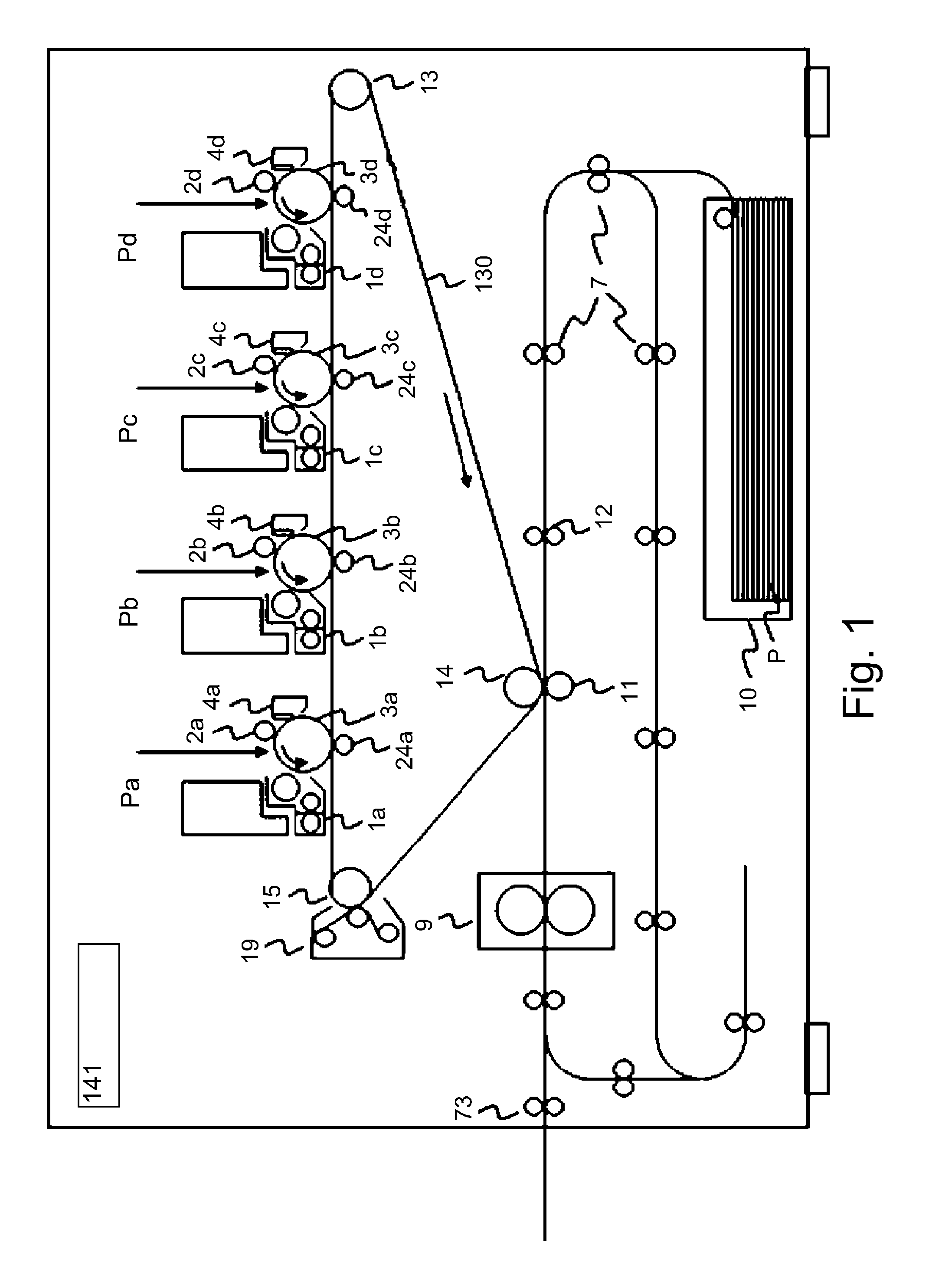
[0017]FIG. 1 is a sectional view of the image forming apparatus. As shown in FIG. 1, the image forming apparatus comprises juxtaposed first, second, third and fourth image forming stations Pa, Pb, Pc, Pd. In these image forming stations, different color toner images are formed through latent image formation, development and transfer processes.
[0018]The image forming stations Pa, Pb, Pc, Pd include photosensitive drums 3a, 3b, 3c, 3d as image bearing members, respectively. On the photosensitive drums 3a, 3b, 3c, 3d, respective color toner images are formed. An intermediary transfer member (intermediary transfer belt) 130 is provided adjacent to the photosensitive drums 3a, 3b, 3c, 3d. Onto the intermediary transfer member 130, the toner images are primary-transferred from the photosensitive drums 3a, 3b, 3c, 3d. The toner images carried on the intermediary transfer member 130 are secondary-transferred onto the sheet P in a secondary transfer portion. The sheet P ...
embodiment 2
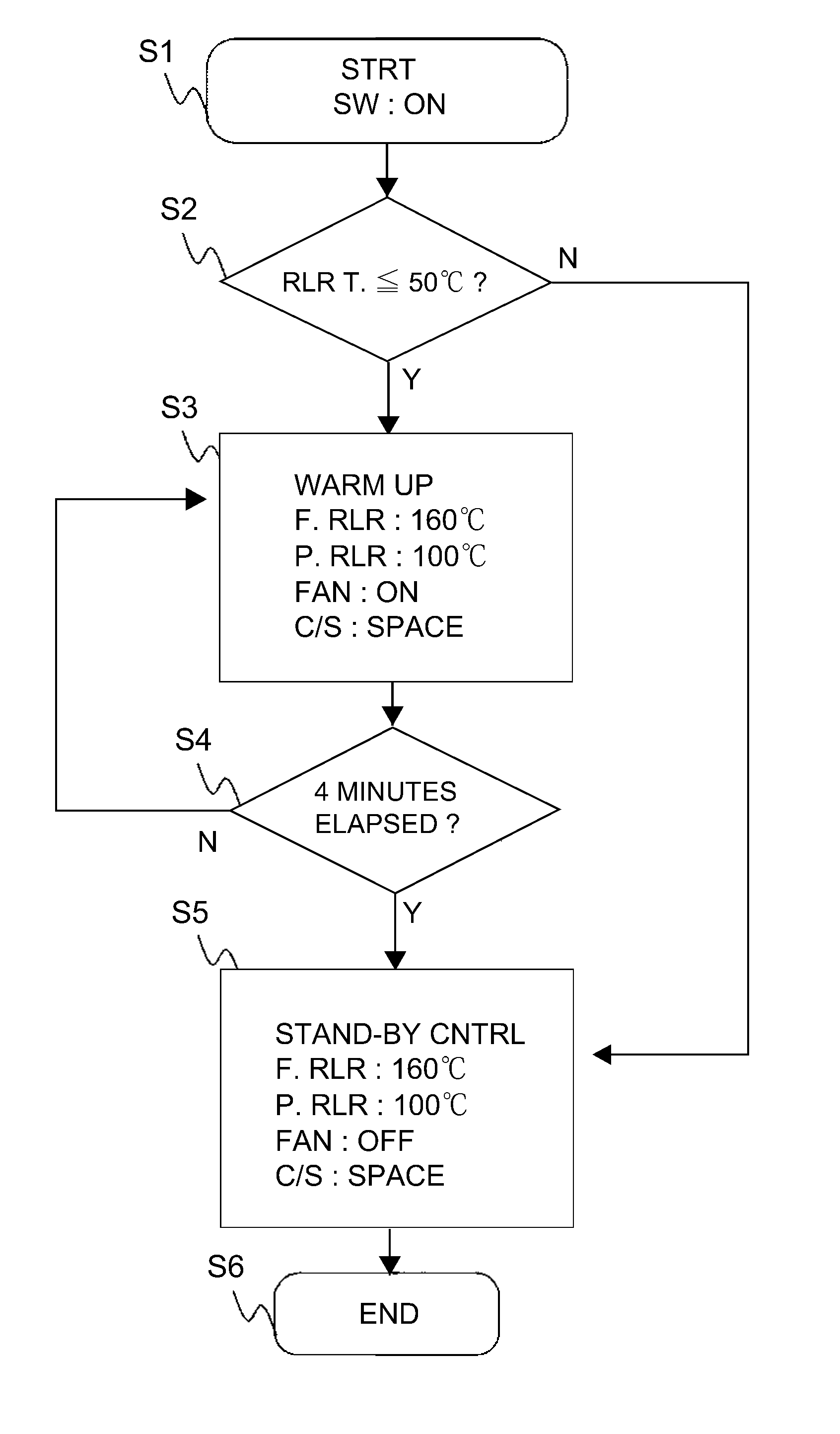
[0065]A fixing device 9 of Embodiment 2 will be described. In Embodiment 1, the air feeding portion 206 is actuated at the beginning of the first-warming-up-control-in-the-morning. On the other hand, in Embodiment 2, the air feeding portion 206 is actuated partway of the first-warming-up-control-in-the-morning. FIG. 6 is a flow chart of a first-warming-up-control-in-the-morning according to Embodiment 2 of the present invention. In the first-warming-up-control-in-the-morning of this embodiment, a first warming-up operation and then a second warming-up operation are carried out. The first warming-up is carried out for 2 minutes, and the second warming-up is carried out for 2 minutes (4 minutes in total).
[0066]The flow of the warming-up control according to Embodiment 2 will be described in detail. When the main voltage source of the image forming apparatus is activated (step S1), the temperature detecting portion 202 detects the temperature of the fixing roller 51. The controller 141...
modified example
[0076]The present invention is not limited to the above-described embodiments, but various modifications can be made within the present invention.
PUM
Abstract
An image forming apparatus includes heating and pressing rollers for fixing a toner image; a contacting and spacing portion for contacting and spacing between the rollers; an air feeder for cooling the pressing roller during a job; a guide for the sheet having been subjected to an image fixing process; an acquiring portion for acquiring the temperature of the guide: and an executing portion for executing a warming-up process of the heating roller and the pressing roller to raise temperatures of the heating roller and the pressing roller, wherein the executing portion controls the contacting and spacing portion and the air feeder so that the air is fed toward the guide through between the heating roller and the pressing roller at least in a part of the warming-up process, when the temperature is lower than a predetermined temperature upon activation of a main voltage source.
Description
FIELD OF THE INVENTION AND RELATED ART[0001]The present invention relates to an image forming apparatus for forming an image on a sheet. The image forming apparatus may be a copyingmachine, a printer, a facsimilemachine, a multifunction machine having a plurality of functions of these machines, or the like.[0002]In a known image forming apparatus, there is provided an image fixing device for heating a toner image formed on the sheet to fix the toner image on the sheet. Japanese Laid-open Patent Application 2013-64790 discloses a fixing device, in which the toner image on the sheet is heated and pressed by a nip forward between a heating roller and a pressing roller.[0003]When the toner image is fixed using such a fixing device (fixing process), there is a likelihood that dew condensation occurs on the feeding path for the sheet. More particularly, by the fixing process of the fixing device, water vapor is produced from the sheet, and the dew condensation occurs by the water vapor ...
Claims
Application Information
Patent Timeline
Application Date:The date an application was filed.
Publication Date:The date a patent or application was officially published.
First Publication Date:The earliest publication date of a patent with the same application number.
Issue Date:Publication date of the patent grant document.
PCT Entry Date:The Entry date of PCT National Phase.
Estimated Expiry Date:The statutory expiry date of a patent right according to the Patent Law, and it is the longest term of protection that the patent right can achieve without the termination of the patent right due to other reasons(Term extension factor has been taken into account ).
Invalid Date:Actual expiry date is based on effective date or publication date of legal transaction data of invalid patent.

